Do not remove the pressure cap from a hot engine. Wait until the coolant temperature is below 50°C [120°F] before removing the pressure cap. Heated coolant spray or steam can cause personal injury.
WARNING
Coolant is toxic. Keep away from children and pets. If not reused, dispose of in accordance with local environmental regulations.
Do not remove the pressure cap from a hot engine. Wait until the coolant temperature is below 50°C [120°F] before removing the pressure cap. Heated coolant spray or steam can cause personal injury.
WARNING
Coolant is toxic. Keep away from children and pets. If not reused, dispose of in accordance with local environmental regulations.
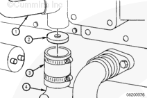
The coolant flow that provides cooling to the torque converter (if equipped) is achieved in different manners.
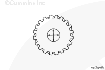
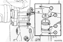
ISM and QSM Series engines use a torque converter cooler disc inside the coolant bypass hose to direct engine coolant to the inlet side of the torque converter cooler.
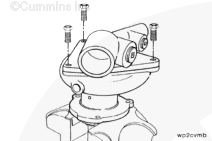
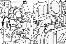
Remove the two water pump water transfer connection capscrews and push the water pump transfer connection into the water pump as far as possible to facilitate water pump removal.
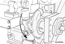
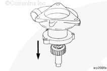
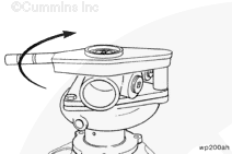
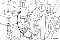
Remove the water pump. Twist the pump outward from the top, and angle the rear of the pump downward, as it is being removed, to allow the pump to pass the thermostat housing support.
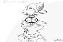
Remove the water pump water transfer connection from the water pump.
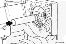
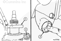
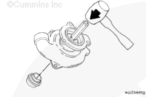
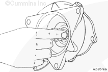
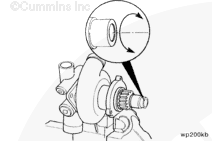
Check the needle bearing for damage and freedom of needle rotation. Replace the bearing if it is damaged or if it does not turn freely.
If the bearing is replaced, use bearing installation tool, Part Number 3824117, along with a cup driver, to remove the needle bearing from the gear housing. Gently tap the bearing out from the rear side of the housing.
The coolant flow that provides cooling to the torque converter (if equipped) is achieved in different manners.
ISM and QSM Series engines use a torque converter cooler disc inside the coolant bypass hose to direct engine coolant to the inlet side of the torque converter cooler.
Remove the water pump. Twist the pump outward from the top, and angle the rear of the pump downward, as it is being removed, to allow the pump to pass the thermostat housing support.
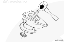
Check the needle bearing for damage and freedom of needle rotation. Replace the bearing if it is damaged or if it does not turn freely.
If the bearing is replaced, use bearing installation tool, Part Number 3824117, along with a cup driver to remove the needle bearing from the gear housing. Gently tap the bearing out from the rear side of the housing.
When using solvents, acids, or alkaline materials for cleaning, follow the manufacturer’s recommendations for use. Wear goggles and protective clothing to reduce the possibility of personal injury.
WARNING
Wear appropriate eye and face protection when using compressed air. Flying debris and dirt can cause personal injury.
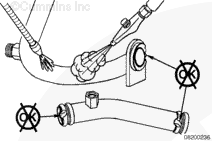
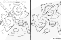
Clean the EGR cooler coolant supply upper and lower tubes with solvent.
Dry with compressed air.
Inspect the EGR cooler coolant supply upper and lower tubes for cracks or other damage. Replace the component, if it is cracked or otherwise damaged.
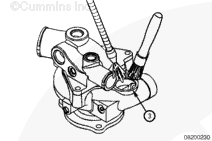
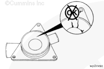
Inspect the water pump housing for cracks or other damage.
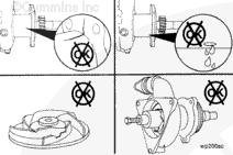
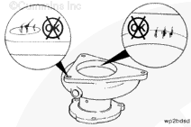
Inspect the water pump weep hole for any indication of leaks.
A streak or chemical buildup at the weep hole is not justification for water pump replacement. If a steady flow of coolant or oil is observed, replace the water pump with a new or rebuilt unit.
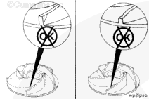
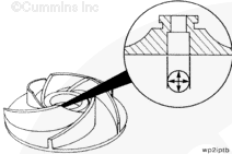
Remove the water pump cover and inspect the water pump impeller for cracks or other damage.
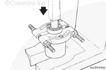
The bearing separator halves must be under the inner race of the bearing to prevent personal injury or bearing damage when the shaft is pushed from the bearing.
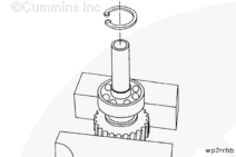
Install a section of pipe 89 mm [3.50 in] outside diameter x 76.2 mm [3.00 in] inside diameter x 89 mm [3.50 in] length in an arbor press to support the bearing separator.
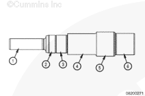
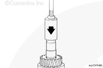
Install the shaft assembly through the section of pipe in the arbor press with the rear bearing inner race supported by bearing separator, Part Number 3375326 or equivalent.
Do not allow the shaft to fall when pressed from the gear. Damage to the shaft or personal injury can occur.
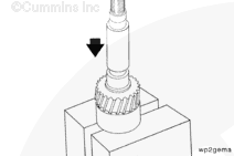
NOTE: Make sure the gear surface and not the shoulder of the shaft is resting on the arbor press.
NOTE: To remove the gear from the shaft requires a 13345 N [3000 lbf] arbor press. Do not remove the gear from the shaft if there is no damage to the gear.
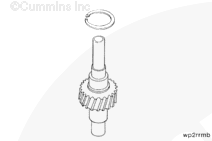
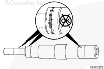
Install the shaft and gear in an arbor press with the largest outside diameter end of the shaft up.
When using solvents, acids, or alkaline materials for cleaning, follow the manufacturer’s recommendations for use. Wear goggles and protective clothing to reduce the possibility of personal injury.
WARNING
Wear appropriate eye and face protection when using compressed air. Flying debris and dirt can cause personal injury.
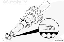
Press against the inner race of the bearing to prevent personal injury or bearing damage.
Install the shaft assembly in an arbor press. Use the water pump bearing mandrel, Part Number 3375318, or equivalent, to support the shaft assembly.
Use the water pump bearing mandrel, Part Number ST-658 or equivalent, to press the bearing on the shaft until the bearing touches the shoulder on the shaft.
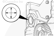
NOTE: Do not lubricate the oil seal. The oil seal must be installed with the lip of the seal and the shaft clean and dry, to provide a proper sealing surface and prevent future water pump and engine damage.
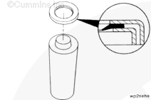
The sealing lip of the oil seal must be installed toward the seal driver.
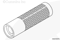
Install the oil seal on the water pump oil seal driver, Part Number 3376139 or equivalent.
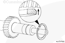
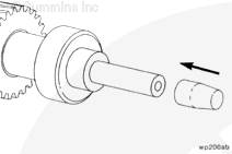
To avoid deformation of the seal lip and water pump leakage, water pump oil seal expander, Part Number 3376387, or equivalent, must be used when installing the shaft assembly.
Install the water pump oil seal expander, Part Number 3376387 or equivalent, on the impeller end of the shaft.
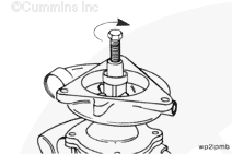
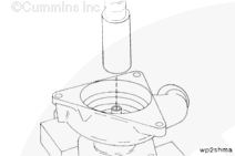
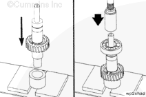
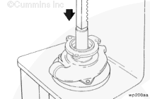
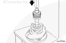
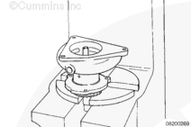
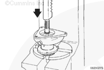
Use service tool, Part Number 3823815, Part Number 4918797 or equivalent, to install the water seal into the service tool. Place the service tool on the arbor press table and install the water seal into the service tool. Place the water pump assembly on top of the tool with the small end of the shaft inserted in the seal. Use the arbor press to press the pump into the seal.
Make sure the arbor press shaft is not to large of a diameter. It should not touch the plastic portion of the impeller or damage to the impeller will occur.
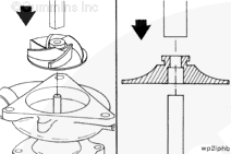
Install the water pump body in an arbor press with the impeller end of the shaft facing up. Support the bottom end of the shaft.
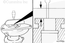
Press the impeller on the shaft until the step inside the impeller bore touches the shaft.
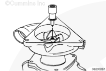
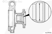
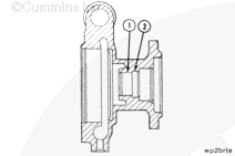
Use a dial depth gauge to measure the distance from the impeller hub to the water pump body surface.
Impeller Hub to Body Surface
mm
in
13.52
MIN
0.532
13.72
MAX
0.540
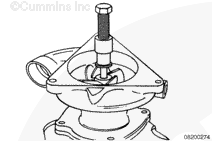
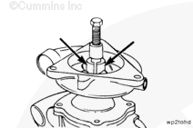
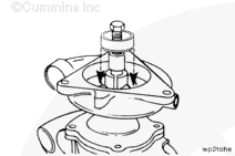
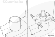
If the distance from the impeller hub to the body surface is greater than the maximum specification, use the water pump impeller puller kit, Part Number 3376542 or equivalent, to move the impeller to the proper distance.
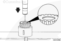
If the needle bearing was removed, use bearing installation tool, Part Number 3824117, to install a new needle bearing in the gear housing.
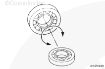
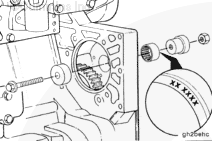
The bearing must be installed with the part number side of the bearing against the installation tool to prevent damage to the bearing during the installation.
Install the bearing from the front side of the gear housing until the bearing is flush with the front edge of the housing bore.
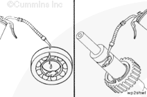
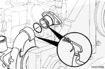
In order to reduce the possibility of pinching or rolling the o-rings during assembly do not lubricate the o-rings. Lubricate the o-ring connection mating surface with clean engine coolant, soapy water, or vegetable oil.
Install the water pump cover. Use a new o-ring.
Torque Value: 47 n.m [35 ft-lb]
Install the water pump water transfer connection into the water pump.
Install a new o-ring on the water pump mounting flange.
The water pump must be twisted outward from the top until the transfer outlet clears the thermostat housing support during installation.
In order to reduce the possibility of pinching or rolling the o-rings during assembly do not lubricate the o-rings. Lubricate the o-ring connection mating surface with clean engine coolant, soapy water, or vegetable oil.
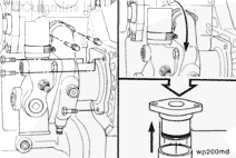
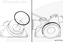
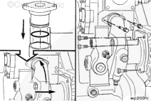
Install a new o-ring on the EGR cooler coolant supply lower tube.
Insert the EGR cooler coolant supply lower tube into the water pump body.
Make sure the EGR cooler coolant supply lower tube is seated completely in the water pump body before tightening the EGR cooler coolant supply lower tube retaining clamp capscrew, to reduce the possibility of pinching the o-ring.
If the needle bearing was removed, use bearing installation tool, Part Number 3824117, to install a new needle bearing in the gear housing.
The bearing must be installed with the part number side of the bearing against the installation tool to prevent damage to the bearing during the installation.
Install the bearing from the front side of the gear housing until the bearing is flush with the front edge of the housing bore.
In order to reduce the possibility of pinching or rolling the o-rings during assembly do not lubricate the o-rings. Lubricate the o-ring connection mating surface with clean engine coolant, soapy water, or vegetable oil.
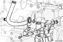
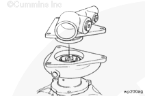
Install a new o-ring on the water transfer tube.
Install the connection into the water pump.
Twist the water pump inward and install the three water pump mounting capscrews.
Torque Value: 47 n.m [35 ft-lb]
Install a new gasket on the water pump water transfer connection. Install and tighten the water transfer connection capscrews.
In order to reduce the possibility of pinching or rolling the o-rings during assembly, do not lubricate the o-rings. Lubricate the o-ring connection mating surface with clean engine coolant, soapy water, or vegetable oil.
Hello, I'm Jack, a diesel engine fan and a blogger. I write about how to fix and improve diesel engines, from cars to trucks to generators. I also review the newest models and innovations in the diesel market. If you are interested in learning more about diesel engines, check out my blog and leave your feedback.
View all posts by Jack
 WARNING







 CAUTION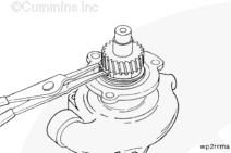



;)
;)
;)
;)
;)
;)
;)
;)
;)
;)
;)
;)
;)
;)
;)
;)
;)
;)
;)
;)
;)
;)
;)
;)
;)
;)
;)
;)
;)
;)
;)
;)
;)
;)
;)
;)
;)
;)
;)
;)
;)
;)
;)
;)
;)
;)
;)
;)
;)
;)
;)
;)
;)
;)
;)
;)
;)
;)
;)
;)
;)
;)
;)
;)
;)
;)
;)
;)
;)
;)
;)
;)
;)
;)
;)
;)
;)
;)
;)
;)
;)
;)
;)
;)
;)
;)
;)
;)
;)
;)
;)
;)
;)
;)
;)
;)
;)
;)
;)
;)
;)
;)
;)
;)
;)
;)
;)
;)
;)
;)
;)
;)
;)
;)
;)
;)
;)
;)
;)
;)
;)
;)
;)
;)
;)
;)
;)
;)
;)
;)
;)
;)
;)
;)
;)
;)
;)
;)
;)
;)