Install
TOC
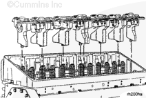
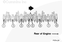
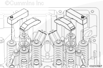
The rocker lever assemblies must be installed in the engine so they are in the same position as they were removed from.
Install the assemblies on the engine.
NOTE : Hand-tighten the mounting capscrews. The rocker lever side clearance must be adjusted before the capscrews are tightened to their final torque value.
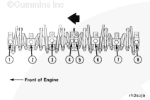
Rocker Lever Installation Side Clearance
Push or use a hammer to tap the number 5 rocker lever support toward the front of the engine.
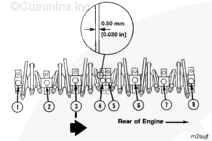
Tighten the mounting capscrews to 5 N•m [44 in-lb].
Install a 0.50 mm [0.020 in] feeler gauge between the number 5 support and the intake lever for the number 4 cylinder.
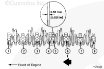
Push or use a hammer to tap the number 6 support toward the front of the engine.
Tighten the mounting capscrews to 5 N•m [44 in-lb].
Install a 0.50 mm [0.020 in] feeler gauge between the number 6 support and the exhaust lever for the number 5 cylinder.
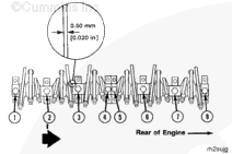
Push or use a hammer to tap the number 7 support toward the front of the engine.
Tighten the mounting capscrews to 5 N•m [44 in-lb].
Install a 0.5 mm [0.020 in] feeler gauge between the number 7 support and the intake lever for the number 6 cylinder.
Push or use a hammer to tap the number 8 support toward the front of the engine.
Tighten the number 5, 6, 7, and 8 support capscrews to their final torque value.
Torque Value: 122 n.m [90 ft-lb]
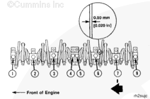
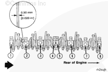
Push or use a hammer to tap the number 4 support toward the rear of the engine.
Tighten the mounting capscrews to 5 N•m [44 in-lb].
Install a 0.50 mm [0.020 in] feeler gauge between the number 4 support and the intake lever for the number 3 cylinder.
Push or use a hammer to tap the number 3 support toward the rear of the engine.
Tighten the mounting capscrews to 5 N•m [44 in-lb].
Install a 0.50 mm [0.020 in] feeler gauge between the number 3 support and the exhaust lever for the number 2 cylinder.
Push or use a hammer to tap the number 2 support toward the rear of the engine.
Tighten the mounting capscrews to 5 N•m [44 in-lb].
Install a 0.50 mm [0.020 in] feeler gauge between the number 2 support and the intake lever for the number 1 cylinder.
Push or use a hammer to tap the number 1 support toward the rear of the engine.
Tighten the number 1, 2, 3, and 4 support capscrews to their final torque value.
Torque Value: 122 n.m [90 ft-lb]
Check the front and rear assemblies for the correct clearance. Check the support capscrews for the correct torque value.
Install the valve crossheads.
NOTE : The crossheads must be installed in the same location from which they were removed.
Engines Equipped with Engine Brakes:
Install the six engine brake crossheads on the exhaust valves. Verify the actuator pins are facing the camshaft side of the engine.
Verify the crossheads are fully seated on the valve stems.
Last Modified: 23-Jan-2009
Published by Jack
Hello, I'm Jack, a diesel engine fan and a blogger. I write about how to fix and improve diesel engines, from cars to trucks to generators. I also review the newest models and innovations in the diesel market. If you are interested in learning more about diesel engines, check out my blog and leave your feedback.
View all posts by Jack


;)
;)
;)
;)
;)
;)
;)
;)
;)
;)
;)
;)
;)
;)
;)
;)
;)
;)
;)
;)