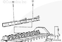
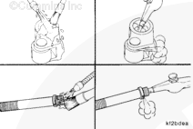
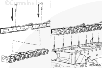
Install the cam follower assembly installation and removal tool, Part Number 3824519. Slide the tool under the assemblies with the supports located in the cutouts on the bottom surface of the tool.
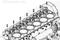
The cam follower assembly consists of two shaft assemblies with a common center support.
Secure the tool to the assemblies by hand-tightening the screws on top of the tool.
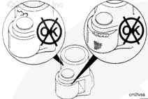
The cam follower levers must be installed in the same position they were removed from. Mark both of the end supports, the center support, and all of the cam followers to identify their location when they are removed. The end supports are not interchangeable. The center support is not interchangeable with any of the other inner supports.
When using solvents, acids, or alkaline materials for cleaning, follow the manufacturer’s recommendations for use. Wear goggles and protective clothing to reduce the possibility of personal injury.
WARNING
Wear appropriate eye and face protection when using compressed air. Flying debris and dirt can cause personal injury.
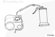
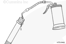
Clean the cam follower parts with solvent and dry with compressed air.
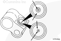
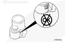
Make sure the oil passages in the cam followers and the cam follower studs are clean.
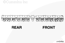
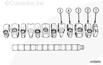
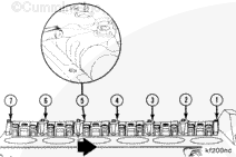
The cam followers, supports, and shafts must be installed in the same position from which they were removed. The shaft end supports are not interchangeable.
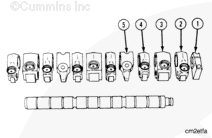
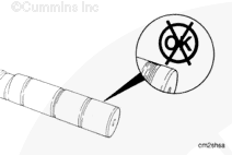
Install the end support (1) on the shaft.
Install the cam followers on the shaft in the following sequence:
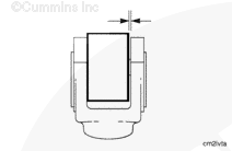
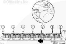
Install a 0.76-mm [0.030 in] feeler gauge between the number three support and the exhaust lever for cylinder number three. Push the number three support toward the No. four support.
Install a 0.76-mm [0.030 in] feeler gauge between the number two support and the intake lever for cylinder number two. Push the number two support toward the number three support.
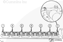
Install the 0.76-mm [0.030 in] feeler gauge between the number five support and the exhaust lever for cylinder number four. Push the number five support toward the number four support.
Install the 0.76-mm [0.030 in] feeler gauge between the number six support and the intake lever for cylinder number five. Push the number six support toward the number five support.
Hello, I'm Jack, a diesel engine fan and a blogger. I write about how to fix and improve diesel engines, from cars to trucks to generators. I also review the newest models and innovations in the diesel market. If you are interested in learning more about diesel engines, check out my blog and leave your feedback.
View all posts by Jack


 WARNING


;)
;)
;)
;)
;)
;)
;)
;)
;)
;)
;)
;)
;)
;)
;)
;)
;)
;)
;)
;)
;)
;)
;)
;)
;)
;)
;)
;)
;)
;)
;)
;)
;)
;)
;)
;)
;)
;)
;)
;)
;)
;)
;)
;)
;)
;)
;)
;)
;)
;)
;)
;)
;)
;)