Batteries can emit explosive gases. To reduce the possibility of personal injury, always ventilate the compartment before servicing the batteries. To reduce the possibility of arcing, remove the negative (-) battery cable first and attach the negative (-) battery cable last.
WARNING
Do not remove the pressure cap from a hot engine. Wait until the coolant temperature is below 50°C [120°F] before removing the pressure cap. Heated coolant spray or steam can cause personal injury.
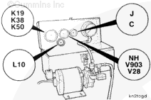
Remove the EGR differential pressure sensor harness and sensor. Refer to Procedure 019-370 in Section 19. This procedure is found in the CM870 Electronic Control System, ISM Engines Troubleshooting and Repair Manual, Bulletin 4021381.
Disconnect the exhaust pressure sensor from the harness. Refer to Procedure 019-376 in Section 19. This procedure is found in the CM870 Electronic Control System, ISM Engines Troubleshooting and Repair Manual, Bulletin 4021381.
Remove the CM870 ECM mounting bracket. Refer to Procedure 019-031 in Section 19. This procedure is found in the CM870 Electronic Control System, ISM Engines Troubleshooting and Repair Manual, Bulletin 4021381.
Remove the refrigerant compressor and mounting bracket.
Batteries can emit explosive gases. To reduce the possibility of personal injury, always ventilate the compartment before servicing the batteries. To reduce the possibility of arcing, remove the negative (-) battery cable first and attach the negative (-) battery cable last.
WARNING
Do not remove the pressure cap from a hot engine. Wait until the coolant temperature is below 50°C [120°F] before removing the pressure cap. Heated coolant spray or steam can cause personal injury.
This component or assembly weighs greater than 23 kg [50 lb]. To prevent serious personal injury, be sure to have assistance or use appropriate lifting equipment to lift this component or assembly.
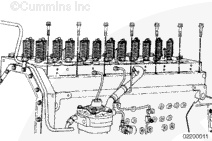
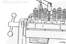
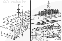
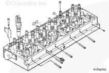
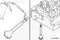
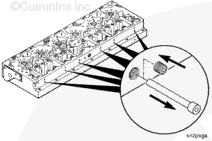
Remove the seven 12-point cylinder head capscrews on the fuel pump side of the engine.
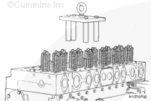
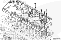
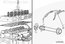
Install cylinder head lifting bracket, Part Number 3822479, with two rocker lever support mounting capscrews and two of the long rocker housing mounting capscrews.
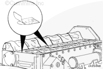
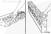
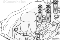
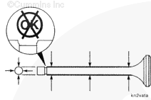
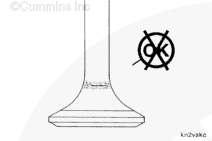
Inspect the valves for indications of leaking or burning. If indications of leaking or burning are found, the valves and the seats must be resurfaced.
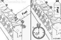
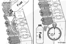
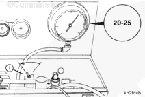
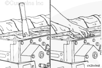
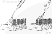
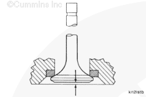
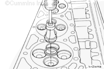
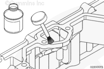
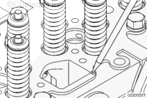
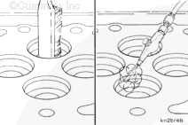
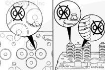
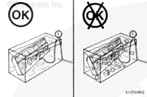
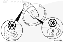
Test the cylinder head for damage. Set the cylinder head down with the exhaust ports facing up. Pour fuel into one of the exhaust ports until it is full. Set the container of fuel down, and start a timer.
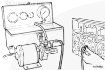
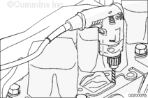
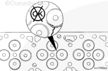
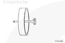
Use the vacuum tester, Part Number ST-1257, to inspect the seal between the valve and the valve seat.
The valve vacuum tester is not recommended for use on used cylinder heads. See the Leak Test section of this procedure for the recommended procedure to check used cylinder heads.
The valve vacuum tester can be used to test all Cummins® engine models. The seal ring, Part Number ST-1257-35, and vacuum cup, Part Number 3376100, are used on the M11 cylinder heads.
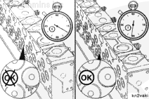
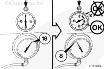
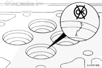
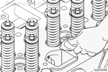
If the elapsed time is less than 10 seconds, perform the following checks:
Repeat the test to be sure the equipment is operating properly.
Use a mallet to hit the valve stem lightly to make sure the valve is seated. Repeat the test.
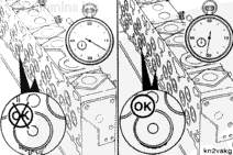
Apply a thin layer of grease on the outside diameters of the insert and the valve head. Repeat the test. The grease pattern will show the point of leakage.
A break in the grease seal pattern will indicate leakage between the valves and valve seat or the valve seat insert and the cylinder head.
When using solvents, acids, or alkaline materials for cleaning, follow the manufacturer’s recommendations for use. Wear goggles and protective clothing to reduce the possibility of personal injury.
WARNING
Wear appropriate eye and face protection when using compressed air. Flying debris and dirt can cause personal injury.
Use a gasket scraper to clean the cylinder block deck surface.
Use Scotch-Brite™ 7448 abrasive pad, Part Number 3823258, or equivalent, and solvent to remove any residual gasket material from the cylinder block deck surface.
Make sure the cylinder head capscrew holes are clean and free of debris, oil, and coolant.
When using solvents, acids, or alkaline materials for cleaning, follow the manufacturer’s recommendation for use. Wear goggles and protective clothing to reduce the possibility of personal injury.
Use Scotch-Brite™ 7448 abrasive pad, Part Number 3823258, or equivalent, and solvent to clean the cylinder head combustion face.
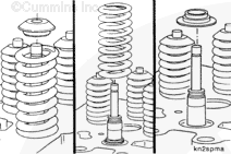
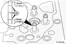
Prior to disassembly, measure and record the valve recess and valve tip height above the top deck of the cylinder head. Refer to the Clean and Inspect for Reuse section in this procedure.
Install a wood block between the valves and head holding fixture to support the valves.
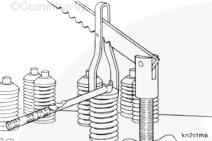
Use the valve spring compressor, Part Number ST-448, the compressor threaded adapter, Part Number 3376850, and the compressor adapter, Part Number 3376851, to compress the valve springs.
Prior to removing the valve guides, measure and record the valve guide inside diameter and height. Refer to the Clean and Inspect for Reuse section of this procedure.
Prior to removing the valve seat inserts, refer to the Leak Test and the Inspect for Reuse sections of this procedure. The condition of the valve, the amount of recess, and the sealing of the valve on the seat insert all help determine whether or not a seat insert needs to be replaced.
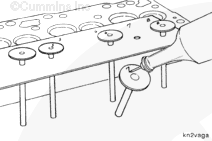
Use slide hammer assembly, Part Number 3376616, and valve seat extractor, Part Number 3376146, to remove the valve seat inserts from the cylinder head.
Inspect the insert bore for cracks or other damage.
If cracks or other damage is found, it is possible to repair the cylinder head by machining the insert bore for oversize valve seat inserts. Reference the Alternative Repair Manual, Bulletin 3710310.
Use Repair Kit, Part Number 4918684, when repairing the cylinder head erosion around the intake port.
Clean the mating face of the rocker lever housing with LPS™ ZeroTri™, or equivalent. Denatured alcohol is also acceptable. Apply Belzona™ Release Agent 9411 around the corresponding intake port with Belzona™ 1311 Ceramic R-Metal. The release agent needs to be applied 15 to 20 minutes prior to contact with the Belzona™ 1311 ceramic R-Metal.
Drill out the eroded sections of the cylinder head, 0.381 mm to 1.02 mm [0.015 in to 0.040 in] deep, for the filler material, with an Irwin™ jetpoint drill bit.
Remove the drill chips from the cylinder head area.
Remove the intake plugs from the ports.
Clean any oil or oil residue away from the gasket surface and the drilled pockets in the cylinder head. Use LPS™ ZeroTri™, or equivalent. Denatured alcohol is also acceptable. Make sure there is no oily residue.
Mix up 3 parts Belzona™ 1311 Base to 1 part Belzona™ Solidifier. It needs to be mixed thoroughly. The color needs to be uniform with no light colored streaks present.
When the surface is clean and dry, apply the mixed Belzona™ 1311 to the drill pockets in the cylinder head. Make sure there is plenty of material to fill the drilled area. Press the filler into the cavity repeatedly to make sure that no air pockets remain.
Install the rocker lever housing only to the cylinder head. Do not use a gasket.
Install the rocker housing bolts in the four corners around the port being repaired. The rocker housing is being used to form the liquid metal to the cylinder head surface.
Tighten the rocker housing bolts.
Torque Value: 61 n.m [45 ft-lb]
Allow the Belzona® to set up for at least 3 hours.
Replace the intake port plugs to prevent debris from entering the cylinder head intake port.
Clean and remove the excessive Belzona® with your finger or a file. Do not allow Belzona® or any debris to fall into the intake port. Blend or smooth the material around the repaired area with a file or abrasive block.
When using solvents, acids, or alkaline materials for cleaning, follow the manufacturer’s recommendations for use. Wear goggles and protective clothing to reduce the possibility of personal injury.
WARNING
Wear appropriate eye and face protection when using compressed air. Flying debris and dirt can cause personal injury.
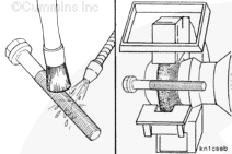
Use a wire brush and solvent to clean the deposits from the valve seat insert bores.
When using solvents, acids, or alkaline materials for cleaning, follow the manufacturer’s recommendations for use. Wear goggles and protective clothing to reduce the possibility of personal injury.
WARNING
Wear appropriate eye and face protection when using compressed air. Flying debris and dirt can cause personal injury.
Use solvent to clean the injector bore.
Dry with compressed air.
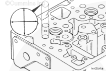
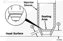
Inspect the injector seat surface in the bottom of the injector bore.
If the bead in the cylinder head is not smooth, the injector bore must be repaired. Reference the L10 Alternative Repair Manual, Bulletin 3810310.
When using solvents, acids, or alkaline materials for cleaning, follow the manufacturer’s recommendations for use. Wear goggles and protective clothing to reduce the possibility of personal injury.
WARNING
Wear appropriate eye and face protection when using compressed air. Flying debris and dirt can cause personal injury.
Use a flexible brush and solvent to clean the valve guide bores in the cylinder head. Dry with compressed air.
Inspect the valves and valve springs for cracks, bent or broken valve stems, broken valve spring collets, or other damage.
Inspect the valves for indications of leaking or burning.
If cracked or damaged parts, or indication of leaking or burning is found, the cylinder head must be rebuilt. Reference the M11 Series Shop Manual, Bulletin 3666075.
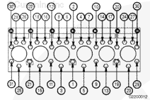
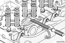
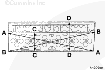
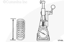
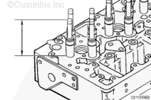
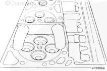
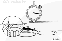
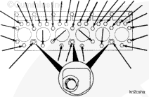
Measure the flatness of the cylinder head combustion face surface as follows:
AA and BB (corner to corner)
CC (across combustion face)
DD (across entire cylinder head surface).
Dimensions CC and DD must be checked from front to rear of cylinder head.
Cylinder Head Flatness
mm
in
AA and BB
0.200
MAX
0.008
CC
0.076
MAX
0.003
DD
0.127
MAX
0.005
If the cylinder head is pitted, has grooves or wear greater than the maximum specified, the cylinder head surface must be machined or cut. Reference the L10 Alternative Repair Manual, Bulletin 3810310.
When using solvents, acids, or alkaline materials for cleaning, follow the manufacturer’s recommendation for use. Wear goggles and protective clothing to reduce the possibility of personal injury.
CAUTION
Do not use caustic or acid solutions to clean the cylinder head capscrews to avoid damage to cylinder head capscrews.
Clean the cylinder head capscrews with a petroleum-based solvent.
Clean the capscrews thoroughly with a wire brush, a wire wheel (soft), or a nonabrasive bead blast to remove deposits from the shank and threads.
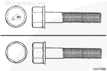
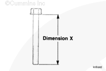
The use of flange cylinder head capscrews with the torque plus angle method of installation places the capscrews beyond the yield point and permanently stretches the capscrews. These capscrews can be reused throughout the life of the engine, unless the capscrew exceeds the specified free length. The free length must be checked to avoid bottoming in the block during installation.
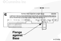
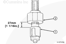
Cylinder head capscrew length gauge, Part Number 3823546, has been designed to check capscrew free length.
NOTE: The new capscrews are coated with grey coating and do not have the 90 degree markings on the capscrew.
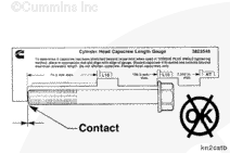
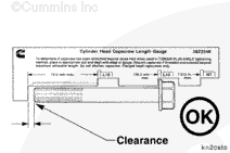
To check the capscrew free length, place the cylinder head of the capscrew in the appropriate slot, long or short, with the flange against the base of the slot.
Use the slot marked for L10 cylinder head capscrews when checking M11 cylinder head capscrews.
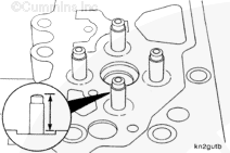
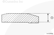
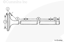
The capscrew can also be checked using a set of calipers. The maximum allowable free length is measured from the bottom of the flange to the end of the capscrew (dimension X).
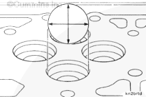
Measure the inside diameter of the valve seat insert bore in the cylinder head.
Insert Bore Inside Diameter (ID)
mm
in
45.920
MIN
1.8079
45.935
MAX
1.8085
If the valve seat insert bore inside diameter does not meet the specifications given.Reference the L10 Alternative Repair Manual, Bulletin 3810310 for the oversize valve installation insert installation.
Measure the inside diameter of the valve guide bore in the cylinder head.
Valve Guide Bore Inside Diameter (ID)
mm
in
16.480
MIN
0.6488
16.500
MAX
0.6496
If the valve guide bore is worn larger than the maximum specified, the valve guide bore can be machined, and a 0.51 mm [0.02 in] oversize valve guide installed. Refer to the L10 Alternative Repair Manual, Bulletin 3810310.
Measure the valve seat insert bore depth in the cylinder head.
Insert Bore Depth (Standard Insert) for Cylinder Heads Built Prior to August 21, 2006
mm
in
9.40
MIN
0.370
9.50
MAX
0.374
Insert Bore Depth (Standard Insert) for Cylinder Heads Built After August 21, 2006 with the Scallop
mm
in
9.15
MIN
0.360
9.25
MAX
0.364
If the valve seat insert bore depth does not meet the specifications given, refer to Cylinder Head Oversize Valve Seat Insert installation in the L10 Alternative Repair Manual, Bulletin 3810310.
Inspect the insert bore for cracks or other damage.
If cracks or other damage is found, it is possible to repair the cylinder head by machining the insert bore for oversize valve seat inserts. Refer to the L10 Alternative Repair Manual, Bulletin 3810310.
When using solvents, acids, or alkaline materials for cleaning, follow the manufacturer’s recommendation for use. Wear goggles and protective clothing to reduce the possibility of personal injury.
WARNING
Wear appropriate eye and face protection when using compressed air. Flying debris and dirt can cause personal injury.
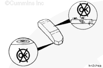
Do not pressure-test the cylinder head with the valves and valve springs installed. Water entering the cylinder head can not be dried thoroughly and will damage the valve guides and valve stems.
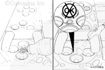
Coolant Passage
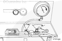
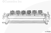
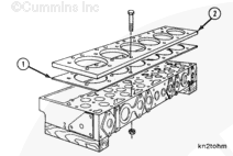
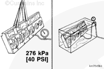
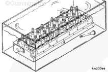
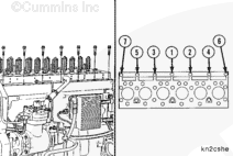
Install cylinder head water test fixture, Part Number 3376082:
Install gasket, Part Number 3376084 (1)
Install test plate, Part Number 3376658 (2)
Install the 32 cylinder head capscrews and 32 (M14 x 1.50) nuts.
This component or assembly weighs greater than 23 kg [50 lb]. To prevent serious personal injury, be sure to have assistance or use appropriate lifting equipment to lift this component or assembly.
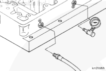
Connect a regulated air supply hose to the test fixture plate. Apply air pressure.
Measurements
kpa
psi
Air Pressure
276
40
Use a nylon lifting strap and a hoist to place the cylinder head in a tank of heated water.
Completely submerge the cylinder head in the water.
This component or assembly weighs greater than 23 kg [50 lb]. To prevent serious personal injury, be sure to have assistance or use appropriate lifting equipment to lift this component or assembly.
WARNING
Wear appropriate eye and face protection when using compressed air. Flying debris and dirt can cause personal injury.
Remove the cylinder head and parts from the cleaning tank.
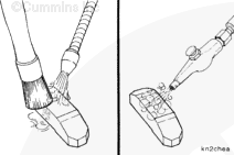
Use fuel passage cleaning brush, Part Number ST-876, to clean the fuel and oil passages with solvent. Dry with compressed air.
Inspect the fuel and oil passages to make sure they are clean.
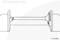
Use the magnetic particle residual method to inspect the valves for cracks.
The exhaust valves contain two types of metal and must be inspected by the coil shot method. There will be a magnetic leakage apparent at the point where the two metals are welded together. The leakage will appear as a wide pattern of magnetic particles.
Magnetize the valves in a coil of 100 to 200 amperes.
The intake valves contain only one type of metal and must be magnetized and inspected in two directions. Use the Magnaglo® coil method and inspect with residual Magnaglo®, the same as for the exhaust valves.
Magnetize the intake valves again with a headshot at 500 to 700 amperes.
When using solvents, acids, or alkaline materials for cleaning, follow the manufacturer’s recommendation for use. Wear goggles and protective clothing to reduce the possibility of personal injury.
WARNING
Wear appropriate eye and face protection when using compressed air. Flying debris and dirt can cause personal injury.
When using solvents, acids, or alkaline materials for cleaning, follow the manufacturer’s recommendation for use. Wear goggles and protective clothing to reduce the possibility of personal injury.
WARNING
Some solvents are flammable and toxic. Read the manufacturer’s instructions before using.
WARNING
Wear appropriate eye and face protection when using compressed air. Flying debris and dirt can cause personal injury.
Remove all magnetism and use solvent to clean the cylinder head. Dry with compressed air.
The cylinder head must be thoroughly cleaned after using the magnetic crack detector to remove all of the iron fragments.
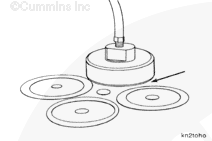
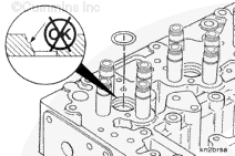
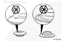
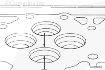
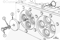
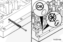
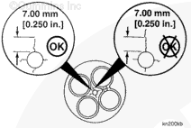
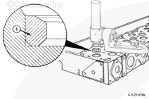
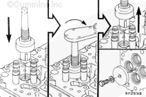
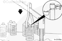
Install the base and swivel of the valve seat insert tool, Part Number ST-275, on the cylinder head to guide the valve seat driver. Install valve guide arbor, Part Number ST-804-1.
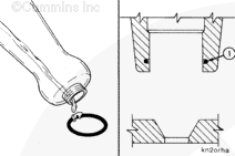
The insert chamfer (1) must be installed toward the bottom of the counterbore.
Use valve seat driver, Part Number 3376105, to drive the valve seat insert into the counterbore.
Make sure the insert is at the bottom of the counterbore.
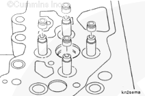
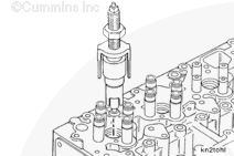
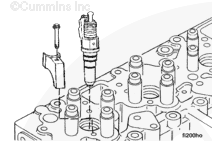
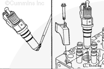
Support the cylinder head in the Part Number ST-583 head holding fixture to reduce the possibility of damage to the injector tip that protrudes from the combustion face.
Install the injectors into the cylinder head without the o-rings.
Do not use excessive force or the seal will be damaged.
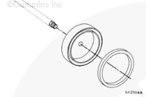
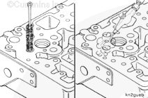
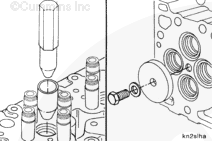
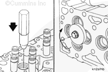
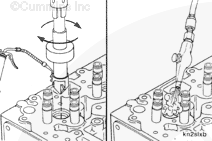
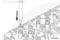
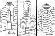
Use valve seal driver, Part Number 3823946, to install the valve seals on the valve guides.
Position the seal on the tool arbor.
Insert the arbor into the top of the guide and tap the tool with a plastic mallet to seat the bottom of the seal against the machined step on the valve guide.
Use valve spring compressor, Part Number ST-448, compressor thread adapter, Part Number 3376850, and compressor adapter, Part Number 3376851, to compress the valve springs.
Always use new collets when rebuilding the cylinder head.
Use vacuum tester, Part Number ST-1257, with vacuum cup, Part Number 3376100, to vacuum test the valve seating. See Cylinder Head – Vacuum Test Valve Seating.
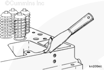
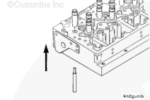
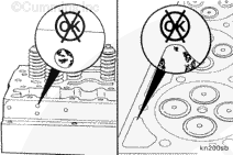
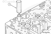
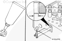
Depending on the fuel plumbing option, one fuel inlet passage insert must be removed to allow fuel to flow to the injectors. If the insert is not removed, the engine will not start.
Remove the pipe plug and use a sharp object to pull the insert from the hole.
Install the cylinder head lifting bracket, Part Number 3822476, with two rocker lever support mounting capscrews and two long rocker housing mounting capscrews.
This component or assembly weighs greater than 23 kg [50 lb]. To prevent serious personal injury, be sure to have assistance or use appropriate lifting equipment to lift this component or assembly.
CAUTION
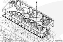
Do not drop the cylinder head on the cylinder head gasket. The gasket material can be damaged.
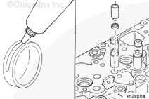
Install the cylinder head gasket.
Use a hoist or hydraulic arm and install the cylinder head.
Use clean 15W-40 oil to lightly coat the cylinder head capscrew threads and bottom of the flange.
Allow the excess oil to drain from the capscrew threads.
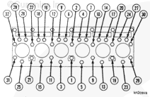
All of the 32 capscrews, old and new, must be rotated 180 degrees after they have been tightened according to torque step 2. Make a mark on the cylinder head as a reference. Rotate the capscrew more than two flats and but less than three flats.
After tightening according to torque step 2, mark the cylinder head as a reference.
When using torque plus angle, the tolerance on the 180-degree angle of rotation is between two and three flats. If the capscrew is unintentionally rotated beyond three flats, do not loosen the capscrew. The clamp load is still acceptable. However, rotating the capscrew beyond three flats reduces the number of potential reuses.
NOTE: This torque procedure is applicable to both old and new capscrews.
NOTE: If the cylinder head or the cylinder head gasket is being replaced due to a malfunction that caused an internal coolant leak, the external crankcase breather element must be replaced, if unit is equipped with an external crankcase breather element.
WARNING
Batteries can emit explosive gases. To reduce the possibility of personal injury, always ventilate the compartment before servicing the batteries. To reduce the possibility of arcing, remove the negative (-) battery cable first and attach the negative (-) battery cable last.
WARNING
Do not remove the pressure cap from a hot engine. Wait until the coolant temperature is below 50°C [120°F] before removing the pressure cap. Heated coolant spray or steam can cause personal injury.
Install the refrigerant compressor and mounting bracket.
Install the CM870 ECM mounting bracket. Refer to Procedure 019-031 in Section 19 in the CM870 Electronic Control System, ISM Engines Troubleshooting and Repair Manual, Bulletin 4021381.
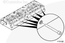
Install the internal wiring harness to the engine.
Connect the Deutsch™ 2-pin connectors to the internal engine wiring harness to the fuel injectors.
Install the internal engine wiring harness holding clamps capscrews.
Install the locking capscrew to the Metri-Pack™ 12-pin connector at the front of rocker lever housing, and connect the connector.Connect the engine brake oil feed line, if equipped.
NOTE: If the cylinder head or the cylinder head gasket is being replaced due to a malfunction that caused an internal coolant leak, the external crankcase breather element must be replaced, if the unit is equipped with an external crankcase breather element.
WARNING
Batteries can emit explosive gases. To reduce the possibility of personal injury, always ventilate the compartment before servicing the batteries. To reduce the possibility of arcing, remove the negative (-) battery cable first and attach the negative (-) battery cable last.
WARNING
Do not remove the pressure cap from a hot engine. Wait until the coolant temperature is below 50°C [120°F] before removing the pressure cap. Heated coolant spray or steam can cause personal injury.
Hello, I'm Jack, a diesel engine fan and a blogger. I write about how to fix and improve diesel engines, from cars to trucks to generators. I also review the newest models and innovations in the diesel market. If you are interested in learning more about diesel engines, check out my blog and leave your feedback.
View all posts by Jack
 WARNING


 CAUTION
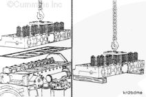


;)
;)
;)
;)
;)
;)
;)
;)
;)
;)
;)
;)
;)
;)
;)
;)
;)
;)
;)
;)
;)
;)
;)
;)
;)
;)
;)
;)
;)
;)
;)
;)
;)
;)
;)
;)
;)
;)
;)
;)
;)
;)
;)
;)
;)
;)
;)
;)
;)
;)
;)
;)
;)
;)
;)
;)
;)
;)
;)
;)
;)
;)
;)
;)
;)
;)
;)
;)
;)
;)
;)
;)
;)
;)
;)
;)
;)
;)
;)
;)
;)
;)
;)
;)
;)
;)
;)
;)
;)
;)
;)
;)
;)
;)
;)
;)
;)
;)
;)
;)
;)
;)
;)
;)
;)
;)
;)
;)
;)
;)
;)
;)
;)
;)
;)
;)
;)
;)
;)
;)
;)
;)
;)
;)
;)
;)
;)
;)
;)
;)
;)
;)
;)
;)
;)
;)
;)
;)
;)
;)
;)
;)
;)
;)
;)
;)
;)
;)
;)
;)
;)
;)
;)
;)
;)
;)
;)
;)
;)
;)
;)
;)
;)
;)
;)
;)
;)
;)
;)
;)
;)
;)
;)
;)
;)
;)
;)
;)
;)
;)
;)
;)
;)
;)
;)
;)
;)
;)
;)
;)
;)
;)
;)
;)
;)
;)
;)
;)
;)
;)
;)
;)
;)
;)
;)
;)
;)
;)
;)
;)
;)
;)
;)
;)
;)
;)
;)
;)
;)
;)
;)
;)
;)
;)