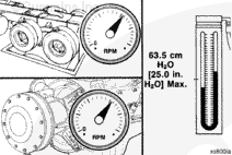
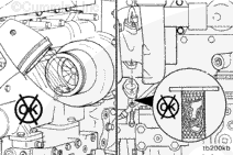
Check the engine breather and the breather tube for restriction. Clear any restrictions found and/or replace any damaged components. Refer to Procedure 003-002 in Section 3.
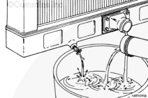
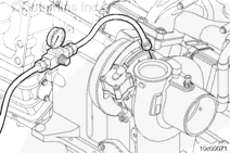
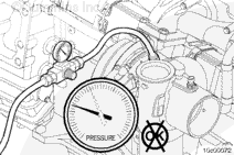
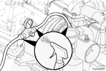
On the automotive engines with CM570, CM870, and CM875, if a bearing housing coolant leak is suspected, use the turbocharger coolant leak test kit, Part Number 3164682.
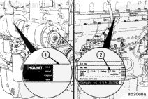
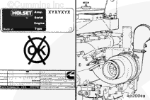
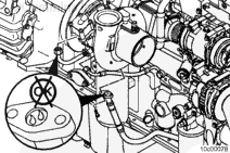
Compare the assembly number (1) on the turbocharger dataplate with the turbocharger specified in the engine control parts list (CPL) number (2) listed on the engine dataplate.
Do not remove the pressure cap from a hot engine. Wait until the coolant temperature is below 50°C [120°F] before removing the pressure cap. Heated coolant spray or steam can cause personal injury.
WARNING
Coolant is toxic. Keep away from children and pets. If not reused, dispose of in accordance with local environmental regulations.
CAUTION
When the lifting eye is installed, it is to be used for lifting the turbocharger only. Lifting additional weight may cause damage to the turbocharger.
CAUTION
When using a lifting eye, make sure the lifting eye is fully engaged in the turbocharger bearing housing and the shoulder of the lifting eye is in contact with the bearing housing.
NOTE: Brush away any loose dirt from around the area of the air handling connections to avoid contamination of the interior of the engine.
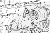
Remove the exhaust connection and inlet air pipe. Refer to Procedure 010-024 in Section 10. Cover open points with caps from the Cummins® Vehicle Air Plumbing Clean Care Kit, Part Number 4919425.
Remove the discharge elbow on the charge-air cooler connection. Refer to Procedure 010-027 in Section 10. Cover open points with caps from the Cummins® Vehicle Air Plumbing Clean Care Kit, Part Number 4919425.
Disconnect the turbocharger speed sensor and compressor air inlet temperature sensors. Use the following procedure in the Electronic Control System Troubleshooting and Repair Manual, Bulletin 4021560. Refer to Procedure 019-390 in Section 19.
Do not remove the pressure cap from a hot engine. Wait until the coolant temperature is below 50°C [120°F] before removing the pressure cap. Heated coolant spray or steam can cause personal injury.
WARNING
Coolant is toxic. Keep away from children and pets. If not reused, dispose of in accordance with local environmental regulations.
CAUTION
When the lifting eye is installed, it is to be used for lifting the turbocharger only. Lifting additional weight may cause damage to the turbocharger.
CAUTION
When using a lifting eye, make sure the lifting eye is fully engaged in the turbocharger bearing housing and the shoulder of the lifting eye is in contact with the bearing housing.
Disconnect the turbocharger speed sensor and compressor air inlet temperature sensors. Refer to Procedure 019-390 in Section 19 in the Electronic Control System Troubleshooting and Repair Manul, Bulletin Number 4021560.
Do no remove the pressure cap from a hot engine. Wait until the coolant temperature is below 50°C [120°F] before removing the pressure cap. Heated coolant spray or steam can cause personal injury.
WARNING
Coolant is toxic. Keep away from children and pets. If not reused, dispose of in accordance with local environmental regulations.
If a wastegated turbocharger is used, remove the wastegate actuator signal line by cutting the crimped hose clamp.
This component weighs 23 kg [50 lb] or more. To avoid personal injury, use a hoist or get assistance to lift this component.
CAUTION
When installing the lifting eye, make sure the shoulder of the lifting eye is bottomed against the bearing housing. Failure to do so can result in failure of the lifting eye and personal injury.
CAUTION
If the lifting eye is installed in the turbocharger bearing housing, it is to be used exclusively for turbocharger removal and installation. It is not to be used in removal of the exhaust manifold, or engine. Doing so will cause damage the turbocharger.
CAUTION
The turbocharger actuator must not be used as a lifting mechanism. Doing so will cause damage to the turbocharger actuator.
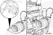
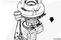
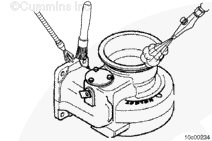
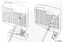
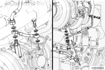
Thread a lifting strap around the turbocharger bearing housing. Take care not to bend the coolant lines when lifting the turbocharger.
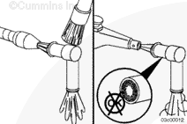
Care must be taken not to damage the turbocharger compressor inlet air temperature sensor, the turbocharger speed sensor, and the turbocharger actuator coolant lines when removing the turbocharger from the engine.
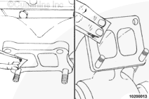
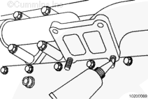
Remove the four turbocharger mounting nuts.
Remove the nuts from the turbocharger studs and remove the turbocharger.
NOTE: If the turbocharger mounting nuts do not loosen freely, split the nuts to avoid breaking a mounting stud.
Remove the turbocharger and discard the gaskets.
Cover the turbocharger exhaust inlet port with a cap from the Air Handling and Vehicle Air Plumbing Clean Care Kits, Part Number 4919403 and 4919425, respectively. Cover the opening on the exhaust manifold with heavy tape.
If the turbocharger is being replaced with a new turbocharger, remove the variable geometry turbocharger actuator.
This component or assembly weighs greater than 23 kg [50 lb]. To prevent serious personal injury, be sure to have assistance or use appropriate lifting equipment to lift this component or assembly.
CAUTION
When installing the lifting eye, make sure the shoulder of the lifting eye is bottomed against the bearing housing. Failure to do so can result in failure of the lifting eye and personal injury.
CAUTION
If the lifting eye is installed in the turbocharger bearing housing, it is to be used exclusively for turbocharger removal and installation. It is not to be used in removal of the exhaust manifold, or engine. Doing so will cause damage the turbocharger.
CAUTION
The turbocharger actuator must not be used as a lifting mechanism. Doing so will cause damage to the turbocharger actuator.
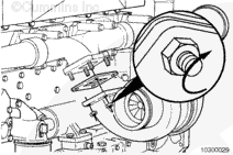
NOTE: ISM CM870 and CM570 – The capscrew in the top of the turbocharger bearing housing can be removed and replaced with a lifting eye to aid in removal of the turbocharger.
Care must be taken not to damage the turbocharger compressor inlet air temperature sensor, the turbocharger speed sensor, and the turbocharger actuator coolant lines when removing the turbocharger from the engine.
Remove the four turbocharger mounting nuts from the turbocharger studs and remove the turbocharger.
NOTE: If the turbocharger mounting nuts do not loosen freely, split the nuts to avoid breaking a mounting stud.
Turbine Housing Replacement for ISM Automotive with CM570, QSM11 with CM570 and Power Generation with CM570
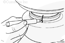
Place the turbocharger outlet on a clean, flat surface. Create an alignment mark on the turbine housing, bearing housing, and the V-band clamp. This mark will make certain the components are oriented correctly during the assembly process.
NOTE: This procedure applies only to ISM Automotive with CM570, QSM11 with CM570, and Power Generation with CM570. Do not disassemble variable geometry turbochargers (VGT).
Turbine blades can be easily damaged and care is required for the turbine housing removal process.
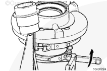
Use a soft hammer to tap the turbine housing down against a soft bench surface.
As the bearing housing and compressor housing assembly loosen, gently lift the assembly out of the turbine housing.
The wastegate mounting is not affected by this disassembly process.
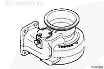
Always clean the turbine housing before assembly, paying particular attention to the surface close to the turbine housing and the bearing housing location.
NOTE: This procedure only applies to Automotive with CM570, QSM11 with CM570, and Power Generation with CM570. Do not use these cleaning procdures on variable geometry turbochargers (VGT).
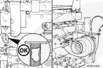
NOTE: The turbocharger turbine housing surface adjacent to the turbine compressor wheels must be clean, smooth, and free from deposits.
Automotive with CM570, QSM11 with CM570, and Power Generation with CM570
Turbocharger Turbine Housing Cleaning
Inspect the components to detect signs of burning and other conditions in order to obtain as much information as possible before washing.
When using solvents, acids, or alkaline materials for cleaning, follow the manufacturer’s recommendations for use. Wear goggles and protective clothing to reduce the possibility of personal injury.
WARNING
Some solvents are flammable and toxic. Read the manufacturer’s instructions before using.
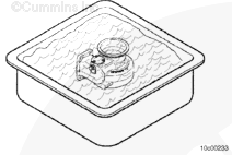
Soak the turbocharger turbine housing in a non-corrosive, low flash point metal cleaner to loosen deposits.
Wear appropriate eye and face protection when using compressed air. Flying debris and dirt can cause personal injury
NOTE: Do not bead blast aluminum and cast iron components together.
NOTE: To prevent bead spray impinging directly on the clamp plate and turbine flange threads, mask off and plug all items.
NOTE: Prevent the bead spray from impinging directly on the wastegate valve spindle, as beads can penetrate the spindle bore, leading to spindle seizure.
It is permissible to bead blast the turbocharger turbine housing if the chemical and brush cleanings are not effective.
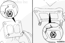
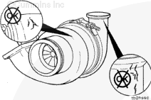
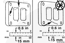
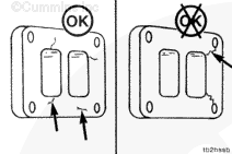
If cracks exist on the outer walls, the housing must be replaced.
A charge-air cooler failure can cause progressive damage to the turbine housing. If the turbine housing is damaged, check the charge-air cooler. Refer to Procedure 010-027 in Section 10.
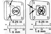
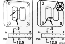
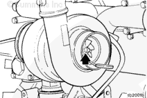
With the feeler gauge in the same location, gently push the compressor wheel away from the compressor housing and measure the clearance between the compressor wheel and the housing.
Subtract the smaller clearance from the larger clearance. This is the radial bearing clearance.
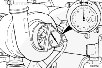
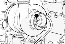
For variable geometry turbochargers, check the radial clearance of the rotor system by pushing the compressor wheel toward the wall of the compressor cover with light finger pressure. The turbocharger passes inspection if the wheel does not contact the compressor cover wall.
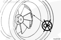
Repeat the procedure on the turbine wheel.
Replace the turbocharger if the radial bearing clearance does not meet specifications.
ISM Automotive with CM570, QSM11 with CM570 and Power Generation with CM570
Install the turbine housing. Position the V-band clamp over the bearing housing and align the ink marks applied during the disassembly process.
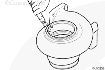
Apply anti-seize compound to the bearing housing locating bore of the turbine housing.
Carefully slide the bearing and compressor housing assembly into the turbine housing. Use the ink alignment mark to locate the turbine housing assembly in the correct orientation with the turbine housing.
This component or assembly weighs greater than 23 kg [50 lb]. To prevent serious personal injury, be sure to have assistance or use appropriate lifting equipment to lift this component or assembly.
CAUTION
When installing lifting eye, make sure the shoulder of the lifting eye is bottomed against the bearing housing. Failure to do so can result in failure of lifting eye and personal injury.
CAUTION
If the lifting eye is installed in the turbocharger bearing housing, it is to be used exclusively for turbocharger removal and installation. It is not to be used in removal of the exhaust manifold, or engine. Doing so will cause damage to the turbocharger.
CAUTION
Do not rotate the turbocharger turbine housing. Loosening the turbine v-band and rotating the turbine housing may cause damage to an internal variable geometry mechanism.
CAUTION
The turbocharger actuator must not be used as a lifting mechanism. Doing so will cause damage to the turbocharger actuator.
Thread a lifting strap around the turbocharger bearing housing. Take care to not bend the coolant lines when lifting the turbocharger.
Care must be taken not to damage the turbocharger compressor inlet air temperature sensor, the turbocharger speed sensor and the turbocharger actuator coolant lines when installing the turbocharger.
Install a new gasket, the turbocharger, and the four mounting nuts. Tighten the mounting nuts.
This component or assembly weighs greater than 23 kg [50 lb]. To prevent serious personal injury, be sure to have assistance or use appropriate lifting equipment to lift this component or assembly.
CAUTION
When installing lifting eye, make sure the shoulder of the lifting eye is bottomed against the bearing housing. Failure to do so can result in failure of lifting eye and personal injury.
CAUTION
If the lifting eye is installed in the turbocharger bearing housing, it is to be used exclusively for turbocharger removal and installation. It is not to be used in removal of the exhaust manifold, or engine. Doing so will cause damage to the turbocharger.
CAUTION
Do not rotate the turbocharger turbine housing. Loosening the turbine v-band and rotating the turbine housing may cause damage to an internal variable geometry mechanism.
CAUTION
The turbocharger actuator must not be used as a lifting mechanism. Doing so will cause damage to the turbocharger actuator.
NOTE: ISM CM870 and CM570 – The capscrew in the top of the turbocharger bearing housing can be removed and replaced with a lifting eye to aid in removal of the turbocharger.
Care must be taken not to damage the turbocharger compressor inlet air temperature sensor, the turbocharger speed sensor and the turbocharger actuator coolant lines when installing the turbocharger.
Install a new gasket, the turbocharger, and the four mounting nuts. Tighten the mounting nuts.
Coolant is toxic. Keep away from children and pets. If not reused, dispose of in accordance with local environmental regulations.
WARNING
Do not remove the pressure cap from a hot engine. Wait until the coolant temperature is below 50°C [120°F] before removing the pressure cap. Heated coolant spray or steam can cause personal injury.
Connect the turbocharger speed sensor and compressor inlet temperature sensors. For the ISM engine, see the following procedure in the Electronic Control System Troubleshooting and Repair Manual, Bulletin 4021560. Refer to Procedure 019-390 in Section 19.
Coolant is toxic. Keep away from children and pets. If not reused, dispose of in accordance with local environmental regulations.
WARNING
Do not remove the pressure cap from a hot engine. Wait until the coolant temperature is below 50°C [120°F] before removing the pressure cap. Heated coolant spray or steam can cause personal injury.
Connect the turbocharger speed sensor and compressor inlet temperature sensors. For ISM engines, see the following procedure in the Electronic Control System Troubleshooting and Repair Manual. Refer to Procedure 019-390 in Section 19.
Coolant is toxic. Keep away from children and pets. If not reused, dispose of in accordance with local environmental regulations.
WARNING
Do not remove the pressure cap from a hot engine. Wait until the coolant temperature is below 50°C [120°F] before removing the pressure cap. Heated coolant spray or steam can cause personal injury.
Hello, I'm Jack, a diesel engine fan and a blogger. I write about how to fix and improve diesel engines, from cars to trucks to generators. I also review the newest models and innovations in the diesel market. If you are interested in learning more about diesel engines, check out my blog and leave your feedback.
View all posts by Jack


 WARNING
  CAUTION


;)
;)
;)
;)
;)
;)
;)
;)
;)
;)
;)
;)
;)
;)
;)
;)
;)
;)
;)
;)
;)
;)
;)
;)
;)
;)
;)
;)
;)
;)
;)
;)
;)
;)
;)
;)
;)
;)
;)
;)
;)
;)
;)
;)
;)
;)
;)
;)
;)
;)
;)
;)
;)
;)
;)
;)
;)
;)
;)
;)
;)
;)
;)
;)
;)
;)
;)
;)
;)
;)
;)
;)
;)
;)
;)
;)
;)
;)
;)
;)
;)
;)
;)
;)
;)
;)
;)
;)
;)
;)
;)
;)