|
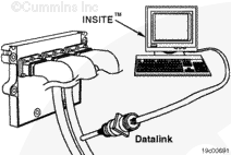
Use INSITE™ electronic service tool and go to the ECM Diagnostic Tests screen.
From the list, select VGT Electronic Actuator Installation and Calibration and click on the “next” button.
NOTE: The VGT Electronic Actuator Installation and Calibration is not a diagnostic test. It is the procedure to properly install and calibrate the turbocharger actuator. Running this procedure improperly can result in additional fault codes and/or damage to the turbocharger or actuator.
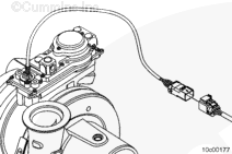
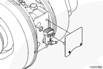
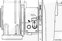
The INSITE™ electronic service tool “INSTALL ACTUATOR” command must only be run with the actuator not mounted to the turbocharger.
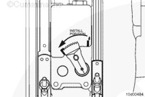
Locate the column labeled “Value” and left click on the down arrow. Select “INSTALL ACTUATOR” and select “START”.
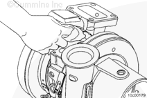
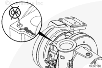
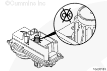
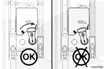
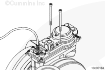
This will set the actuator pinion gear to a known position to prepare it for installation to the turbocharger. This step should take less than 30 seconds to complete with INSITE™ electronic service tool.
INSITE™ electronic service tool will indicate when this step is complete.
Fault Code 2449 will be active at this point in the procedure. Continue through the turbocharger actuator procedure before troubleshooting fault codes.
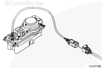
If at any point, INSITE™ electronic service tool status message indicates the procedure was stopped or failed, leave the keyswitch ON and cycle the power to the actuator by unplugging it from the harness, and then reconnecting it.
If cycling the power to the actuator does not work, unplug the actuator, turn the keyswitch OFF for 30 seconds, and then restart INSITE™ electronic service tool. Then start over, beginning with the “INSTALL ACTUATOR” step.
|

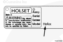
 WARNING


 CAUTION
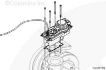


;)
;)
;)
;)
;)
;)
;)
;)
;)
;)
;)
;)
;)
;)
;)
;)
;)
;)
;)
;)
;)
;)
;)
;)
;)
;)
;)
;)
;)
;)
;)
;)
;)
;)
;)
;)
;)
;)
;)
;)