General Information |
|||||||||||||||||||||||||||||||||||||
|
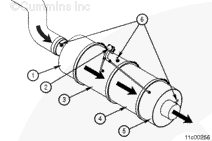
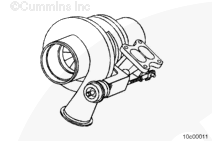
Exhaust gas is recirculated through the engine to reduce the amount of Oxides of Nitrogen (NOx) emitted from the engine. The exhaust gas is cooled as it flows through the EGR cooler, and then is mixed with the compressed fresh air from the turbocharger before entering the intake manifold. EGR was introduced to reduce the amount of in-cylinder oxygen available for combustion while maintaining the same amount of flow through the engine. Exhaust gases present during the start of combustion are very stable and have a very slow reaction rate. They absorb heat during combustion, resulting in lower in-cylinder peak flame temperatures and therefore lower NOx emissions. The EGR mixer was designed to completely mix the EGR gas with the turbocharged air from the charge air cooler. Complete mixing is necessary to provide smooth operation and decreased emissions. The EGR valve is controlled by the electronic control module (ECM). ISM with CM870 engines control the EGR valve by a pulse width modulated signal sent by the ECM and operates between 0 percent and 100 percent open. When the EGR valve is open, exhaust gas flows from the hot side of the engine, through the EGR cooler, and into the EGR mixer. ISM with CM876 engines control the EGR valve through a J1939 datalink signal sent by the ECM and operates between 0 percent and 100 percent open. When the EGR valve is open, exhaust gas flows from the EGR cooler through the EGR connection tube, and into the EGR mixer. The ISM with CM876 EGR connection tube allows the flow of cooled exhaust gas from the EGR valve outlet at the rear of the engine to the EGR mixer before the intake manifold. This engine utilizes a two-piece EGR connection tube design which also includes the EGR venturi tube. The ISM CM870 and ISM CM875 EGR connection tube allows the flow of cooled exhaust gas from the EGR cooler outlet at the rear of the engine to the EGR mixer before the intake manifold. This engine utilizes a two-piece EGR connection tube which also includes the EGR venturi tube. The EGR venturi tube contains a flow orifice that is used to measure the amount of exhaust gas flow using an EGR differential pressure sensor and a high and reference differential pressure sensing tubes. The exhaust manifold for the ISM with CM876 engine was redesigned to include a metal seal within the slip joints in efforts to reduce leakage. The exhaust manifold also has a port near the number one exhaust port for the exhaust pressure sensor. The variable geometry turbocharger is required for several important engine operating conditions. It is used to facilitate EGR flow through the engine. Refer to Procedure 010-999 in Section F for further information regarding variable geometry turbocharger and EGR flow interactions. The variable geometry turbocharger is also used for engine braking. The variable geometry mechanism closes in order to increase exhaust manifold pressure. The increased exhaust pressure works against the pistons on the exhaust stroke retarding engine speed.
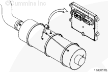
Aftertreatment injection requires that temperatures in the aftertreatment system reach approximately 288°C [550°F]. At this temperature and above, the small quantities of fuel injected into the exhaust will properly oxidize across the aftertreatment diesel oxidation catalyst creating the additional heat required to actively regenerate the aftertreatment diesel particulate filter. Once the warm up phase is complete and the aftertreatment injection has begun, the active regeneration phase begins. During active regeneration, the engine ECM monitors the exhaust temperatures before and after the aftertreatment diesel particulate filter and maintains the temperatures in a range of approximately 427 to 649°C [800 to 1200°F]. The quantity of fuel used for aftertreatment injection will vary as the temperature is controlled within these limits. The temperatures achieved during active regeneration are typically higher than those achieved during passive regeneration. The conversion of soot to carbon dioxide occurs much faster as temperatures increase. A typical active regeneration event will take approximately 20 to 40 minutes to complete while the vehicle is operating. The vehicle operator may notice additional turbocharger noise during this time, along with an illuminated high exhaust temperature lamp, if equipped. The frequency at which an engine will require an active regeneration varies greatly from application to application. In general, vehicles with a low vehicle speed, such as urban vehicles, or a low-load duty cycle, will require more active regeneration events than a heavily loaded vehicle or a vehicle with a high speed duty cycle. The engine ECM also contains a time-based feature for active regenerations which is used to verify correct aftertreatment operation when the vehicle duty cycle is typically high enough that active regeneration events are not necessary. Under some operating conditions, such as low speed, low load, or stop and go duty cycles, the engine may not have enough opportunity to regenerate the aftertreatment diesel particulate filter during normal vehicle operation. When this occurs, the engine illuminates the aftertreatment diesel particulate filter lamp to inform the vehicle operator that assistance is required, typically in the form of a stationary (parked) regeneration. Stationary (parked) regeneration is a form of active regeneration that is initiated by the vehicle operator when the vehicle is not moving. The following procedure provides more information on Stationary (Parked) regeneration. Refer to Procedure 014-013 in Section 14.
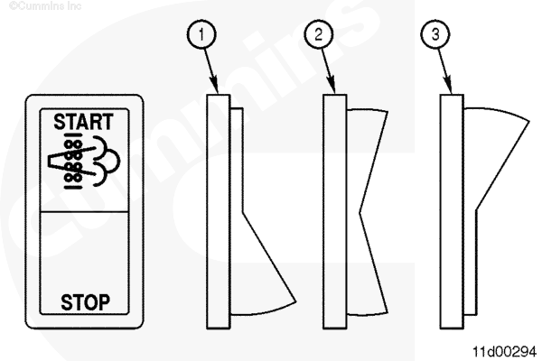
The vehicle manufacturer has the that option of installing two switches that control aftertreatment functions: the start switch and the permit switch. The start switch (known as the Diesel Particulate Filter Regeneration Start Switch in INSITE™ electronic service tool) is used to start a stationary (parked) regeneration. The vehicle manufacturer may also reference this switch as a stationary regeneration switch, start switch, or parked regeneration switch. The permit switch (known as the Diesel Particulate Filter Permit Switch in INSITE™ electronic service tool) is used to allow the vehicle operator to disable active regeneration, if necessary. The vehicle manufacturer may also reference this switch as an inhibit switch, stop switch, or disable switch. The following procedure describes the switch operation and troubleshooting steps. Refer to Procedure 011-056 in Section 11. Automotive with CM570
|
|||||||||||||||||||||||||||||||||||||
;)
;)
;)
;)
;)
;)
;)
;)
;)
;)
;)
;)