General Information |
|||||||||||||||||||||||||||||
|
Variable Geometry Turbocharger: A variable geometry turbocharger is used on the automotive with CM870, automotive with CM875 and automotive with CM876 engines to maximize the performance of the engine and also to help decrease emissions levels. Variable geometry turbochargers have quicker response time, and quicker engine deceleration for quicker shifting than fixed geometry turbochargers. Because of the active control of the variable geometry turbocharger, the intake manifold pressure and turbocharger sound can often change. There is not a loss of power associated with the change in intake manifold pressure; however, customer perception of engine power can be affected. Typically, when the intake manifold pressure and turbocharger sound are changing during steady state operation, the ECM is adjusting the EGR flow into the engine and the engine’s power is not affected. When the throttle is released, perhaps for a gear change, the variable geometry actuator closes. This prepares the turbocharger to be ready to build intake manifold pressure quickly to provide improved turbocharger response when the throttle is depressed after the gear change. Because of this design for improved turbocharger response, after releasing the throttle, the engine speed of the ISM engine with a variable geometry turbocharger can decrease more quickly than an engine without a variable geometry turbocharger. Fast deceleration of engine speed can cause the drivers to adjust shifting styles until becoming accustomed to the different deceleration speeds. Due to the variable geometry mechanism being contained inside the turbine housing, it is mandatory that the V-band clamp is not disturbed during turbocharger servicing. Loosening the V-band clamp and rotating the bearing housing or turbine housing can cause the variable geometry mechanism to jam and the turbocharger to fail. Service turbochargers with the proper turbine housing orientation are available so that no adjustments are necessary. Similar to all of Cummins® electronically controlled heavy duty engines, the ISM engine with variable geometry turbocharger incorporates a power derate to protect the turbocharger from damage while operating in high altitudes. The variable geometry turbocharger meets or exceeds the power output of the engines with a fixed geometry turbocharger at most altitudes. At and around 2.438 km [8000 ft] elevation, however, a slight power decrease can be noticeable when operating the engine with a variable geometry turbocharger and comparing its performance to an engine with a fixed geometry turbocharger. Automotive with CM875 The automotive CM875 and CM870 engines with variable geometry turbocharger is pneumatically actuated with air from the OEM air tanks. High air pressure from the turbocharger control valve closes the variable geometry mechanism, which increases the exhaust gas pressure and facilitates EGR flow through the engine. A closing variable geometry mechanism also increases turbocharger speed and intake manifold pressure under certain engine operating conditions. Lower air pressure from the turbocharger control valve opens the variable geometry mechanism, which decreases exhaust gas pressure, turbocharger speed, and intake manifold pressure under certain engine operating conditions.
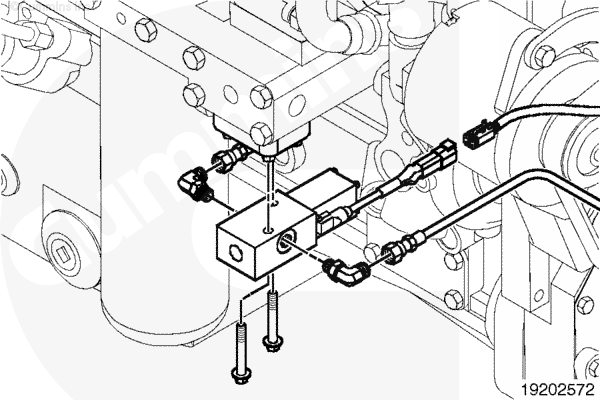
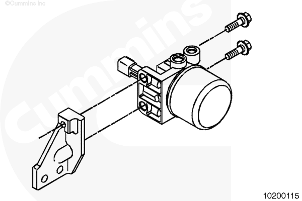
With CM870 – Low Mount Turbocharger Control Valve Automotive CM870 engines use both the turbocharger control valve, which is located below the lubricating oil cooler, along with an air filter and shutoff valve assembly. The air filter and shutoff valve assembly is mounted on the front gear housing, on the fuel pump side of the engine. See Figure 1 and Figure 2.
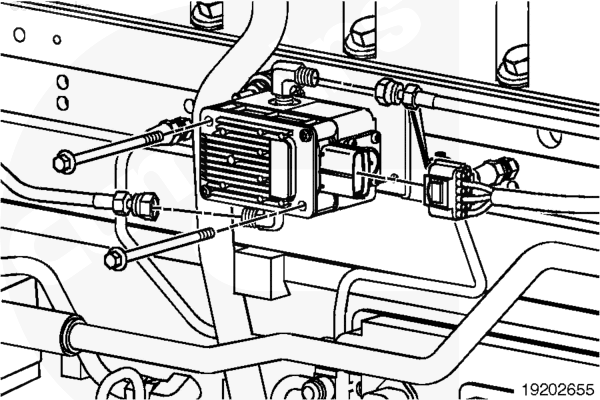
Automotive with CM875 – High Mount Turbocharger Control Valve The automotive CM875 engines use the high mount turbocharger control valve. The high mount turbocharger control valve does not require an air filter. However, the vehicle must be equipped with an air dryer to meet engine installation requirements. The vehicle air supply will be plumbed directly to the control valve inlet port identified as port (1). The outlet air supply port to the variable geometry turbocharger is identified as port (2).
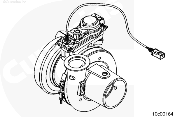
Automotive with CM876 The automotive with CM876 variable geometry turbocharger is electronically actuated. The electronic control module (ECM) sends a command directly to the variable geometry actuator mounted on the turbocharger. See Figure 4. Closing the variable geometry mechanism increases the exhaust gas pressure, facilitating EGR flow through the engine. The turbocharger speed and intake manifold pressure will also increase when the variable geometry mechanism closes, under certain engine operating conditions. Closing the variable geometry turbocharger will also increase the exhaust gas temperature, under certain normal engine operating conditions, and during the aftertreatment regeneration event. This is used to improve the aftertreatment component efficiency. Refer to Procedure 011-999 in Section F for further information regarding the variable geometry turbocharger and aftertreatment system interactions. Opening the variable geometry mechanism decreases exhaust gas pressure, turbocharger speed, and intake manifold pressure under certain engine operating conditions.
|
|||||||||||||||||||||||||||||
;)
;)
;)
;)
;)
;)
;)
;)
;)
;)
;)
;)
;)
;)
;)
;)