Flow Diagram
|
TOC |
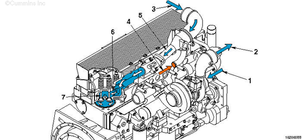
Automotive Applications with EGR
- Intake air inlet to turbocharger
- Turbocharger air to charge-air cooler
- Charge-air cooler to intake manifold
- Exhaust gas to EGR mixer
- Air intake connection
- Intake valve port
- Intake valves.
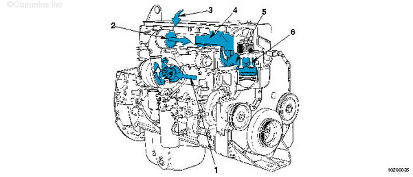
Automotive Applications Without EGR
- Filtered intake air to turbocharger
- Turbocharger air to charge-air cooler
- Charge-air cooler intake air to intake manifold
- Intake manifold
- Intake valve ports
- Intake valves.
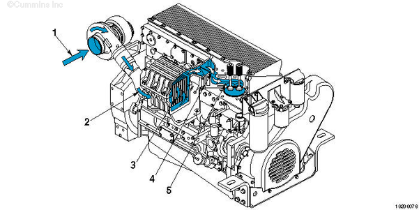
Marine Applications
- Filtered intake air to turbocharger
- Turbocharger air to aftercooler
- Intake air through the aftercooler
- Aftercooled air through intake manifold
- Intake valve ports.
Industrial and Generator Drive
- Filtered intake air to turbocharger
- Turbocharger air to charge air cooler
- Charge air cooler intake air to intake manifold
- Intake manifold
- Intake valve ports
- Intake valves.
|
Last Modified: 23-Jan-2009
Published by Jack
Hello, I'm Jack, a diesel engine fan and a blogger. I write about how to fix and improve diesel engines, from cars to trucks to generators. I also review the newest models and innovations in the diesel market. If you are interested in learning more about diesel engines, check out my blog and leave your feedback.
View all posts by Jack
;)
;)
;)
;)
;)
;)