|
No air will be heard (i.e., leaking noise) through a functional wastegate capsule.
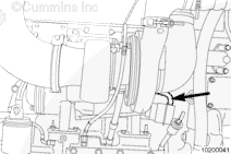
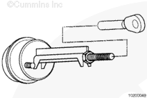
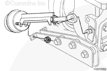
Connect clean regulated air pressure and a pressure gauge to the actuator.
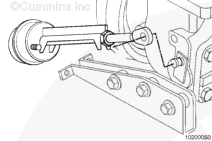
Apply a regulated air pressure to the wastegate actuator to measure travel.
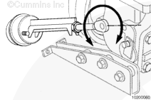
ISM: 117 kPa [17 psi]
QSM: 170 kPa [24.7 psi]
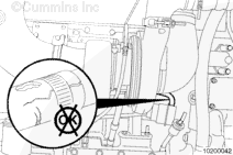
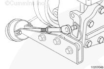
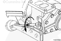
The actuator rod will extend 5.33 mm [0.021 in] to 10.41 mm [0.041 in] in when the air pressure is applied.
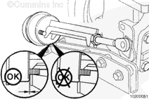
If less than 5.33 mm [0.021 in], or no movement of the actuator rod and lever is detected, remove the turbocharger from the engine and perform the OFF engine test.
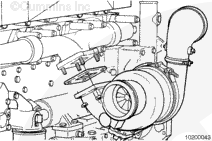
Refer to Procedure 010-033 in Section 10 for turbocharger removal.
Procedure for OFF engine test.
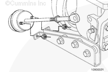
Connect clean, regulated air pressure and a pressure gauge to the actuator.
Apply a regulated air pressure to the wastegate actuator to measure travel.
ISM: 117 kPa [17 psi]
QSM: 170 kPa [24.7 psi]
The actuator rod will extend 5.33 mm [0.021 in] to 10.41 mm [0.041 in] when the air pressure is applied.
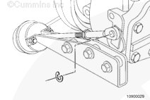
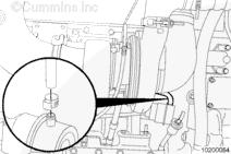
If less than 5.33 mm [0.021 in], or no movement of the actuator rod and lever is detected, remove the actuator rod from the pin.
Actuate the wastegate lever by hand.
If the lever moves, replace the actuator, if the lever does not move, replace the turbocharger.
|

 CAUTION
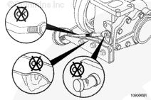


 WARNING
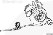


;)
;)
;)
;)
;)
;)
;)
;)
;)
;)
;)
;)
;)
;)
;)
;)
;)
;)
;)
;)
;)
;)
;)
;)
;)
;)
;)
;)
;)
;)