NOTE: Removal of the sensor tubes does not require sensor removal. Sensor removal is necessary only if the sensor adapter is being replaced.
Remove the exhaust gas pressure sensor if the adapter is being replaced. Refer to Procedure 019-376 in Section 19. Reference the Troubleshooting and Repair Manual, CM870 Electronic Control System, ISM Engines, Bulletin 4021381.
NOTE: If the EGR cooler is being replaced due to damage that allowed coolant to leak into the EGR differential pressure sensor tubes, the tubes must be replaced.
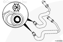
Check the inside of the tubes.
If a tube is clogged or partially clogged, replace the tube.
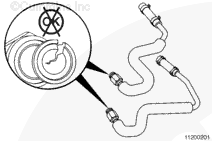
Check the tubes for cracks or thread damage.
Replace the tubes if they are cracked or the threads are damaged.
When using solvents, acids, or alkaline materials for cleaning, follow the manufacturer’s recommendations for use. Wear goggles and protective clothing to reduce the possibility of personal injury.
WARNING
Wear appropriate eye and face protection when using compressed air. Flying debris and dirt can cause personal injury.
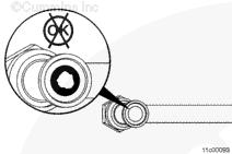
Inspect the mating orifices for the EGR crossover tubes.
If clogged, saturate the carbon deposit with a mineral based solvent, or equivalent.
Carefully clean the debris from the mouth of the orifice, making sure not to damage the orifice.
When using solvents, acids, or alkaline materials for cleaning, follow the manufacturer’s recommendations for use. Wear goggles and protective clothing to reduce the possibility of personal injury.
WARNING
Wear appropriate eye and face protection when using compressed air. Flying debris and dirt can cause personal injury.
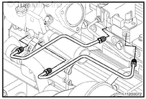
Check the inside of the tubes.
If a tube is partially clogged, saturate the inside of the tube with a mineral based solvent, or equivalent.
Carefully clean the debris from the mouths of the tubes. Make sure not to damage the tube.
If a tube is fully clogged or otherwise unable to be cleaned, replace the tube.
Clean the tube with safety solvent.
Dry with compressed air.
Check the tubes, hose, and hose clamps for cracks or thread damage.
Replace the tubes if the tubes or hose is damaged.
When using solvents, acids, or alkaline materials for cleaning, follow the manufacturer’s recommendations for use. Wear goggles and protective clothing to reduce the possibility of personal injury.
WARNING
Wear appropriate eye and face protection when using compressed air. Flying debris and dirt can cause personal injury.
Inspect the mating orifices for the EGR crossover tubes.
If clogged, saturate the carbon deposit with a mineral based solvent, or equivalent.
Carefully clean the debris from the mouth of the orifice, making sure not to damage the orifice.
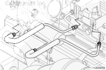
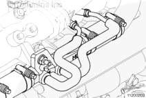
Loosen the EGR differential pressure sensor adapter mounting capscrews, but do not remove. This is so the tubes are not distorted during installation.
Make sure not to cross-connect tubes or a fault code will result.
Apply a light lubricant (CRC 3-36, WD-40, or equivalent) to the tube threads and install the tubes. The lubricant must be applied inside the tube nut, directing the spray on the threads and around the sleeve and flange area.
Tighten the tube nuts.
Torque Value: 16 n.m [142 in-lb]
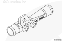
Position the insulation on the differential pressure sensor tubes so the tube nuts at the venturi connection are covered.
The insulation on the pressure tubes is designed to only cover the bottom portion of the tube which threads into the EGR transfer tube. This location proves to be most effective and prevents heat soaking of the EGR differential pressure sensor.
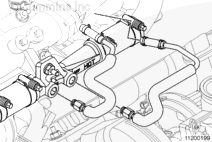
Make sure not to cross-connect tubes or a fault code will result.
Apply a light lubricant (CRC 3-36, WD-40, or equivalent) to the tube threads and install the tubes. The lubricant must be applied inside the tube nut, directing the spray on the threads and around the sleeve and flange area
Tighten the tube nuts at the venturi connections.
Torque Value: 26 n.m [230 in-lb]
Tighten the hose clamps at the differential pressure sensor adapter.
Position the insulation on the differential pressure sensor tubes so that the tube nuts at the venturi connection are covered.
The insulation on the pressure tubes is designed to cover only the bottom portion of the tube which threads into the EGR transfer tube. This is the most effective location and reduces the possibility of heat soaking of the EGR differential pressure sensor.
If removed, install the exhaust gas pressure sensor. Refer to Procedure 019-376 in Section 19. Reference the Troubleshooting and Repair Manual, CM870 Electronic Control System, ISM Engines, Bulletin 4021381.
Start the engine and verify proper operation. Reference the Troubleshooting and Repair Manual, CM870 Electronic Control System, ISM Engines, Bulletin 4021381.
Check for fault codes and leaks.
If damage resulted in coolant, oil, excessive fuel, or excessive black smoke entering the exhaust system, the aftertreatment system must be inspected. Refer to Procedure 014-013 in Section 14.
Hello, I'm Jack, a diesel engine fan and a blogger. I write about how to fix and improve diesel engines, from cars to trucks to generators. I also review the newest models and innovations in the diesel market. If you are interested in learning more about diesel engines, check out my blog and leave your feedback.
View all posts by Jack


 WARNING


;)
;)
;)
;)
;)
;)
;)
;)
;)
;)
;)
;)
;)
;)
;)
;)
;)
;)
;)
;)
;)
;)