ISM, ISMe, and QSM11 – 011-025   EGR Connection Tubes

Preparatory Steps

TOC

 WARNING 

Wear safety glasses or a face shield, as well as protective clothing, to prevent personal injury when using a steam cleaner or high-pressure water.
 WARNING 

The differential pressure sensor tube can be hot. To avoid personal injury, allow the engine to cool before removing.

Use steam or high-pressure water to clean the rear of the engine, specifically around the EGR connection tube area.

SMALL | MEDIUM | LARGE

Remove

TOC

Automotive with CM875, CM870 and CM570


Loosen the EGR return tube mounting capscrews.

Remove the v-band clamp connecting the EGR cooler to the EGR connection tube.

Remove the capscrews and EGR connection tube.

Remove the EGR hose that connects the EGR mixer to the EGR connection tube.

Discard the gasket.

Discard the hose and hose clamps if damaged.

SMALL | MEDIUM | LARGE
   

Automotive with CM876


Loosen the EGR return tube mounting capscrews from the EGR valve outlet port and all EGR return tube hoses.

In order to remove the lower capscrew from the EGR return tube and the EGR valve outlet port, it will be necessary to loosen the EGR cooler outlet v-band clamp and move it forward onto the metal bellows shield.

Remove and discard the gasket between the EGR cooler gas outlet and the EGR valve inlet.

Remove the EGR venturi tube mounting stud and the EGR venturi tube.

Discard the hoses and gasket.

After removal of the component, cover all open points with protective caps from the Air Handling Clean Care Kit or with heavy tape, if needed.

SMALL | MEDIUM | LARGE
   

Clean and Inspect for Reuse

TOC

Automotive with CM875, CM870 and CM570


 WARNING 

When using solvents, acids, or alkaline materials for cleaning, follow the manufacturer’s recommendations for use. Wear goggles and protective clothing to reduce the possibility of personal injury.
 WARNING 

Wear appropriate eye and face protection when using compressed air. Flying debris and dirt can cause personal injury.

Clean the connection tube with safety solvent.

Dry with compressed air.

Check the ends and mating joints of the connection tube and v-band for cracks or any other damage.

Replace if cracks or other damage is found.

SMALL | MEDIUM | LARGE
   

Automotive with CM876


 WARNING 

When using solvents, acids, or alkaline materials for cleaning, follow the manufacturer’s recommendations for use. Wear goggles and protective clothing to reduce the possibility of personal injury.
 WARNING 

Wear appropriate eye and face protection when using compressed air. Flying debris and dirt can cause personal injury.

Clean the connection tube with safety solvent.

Dry with compressed air.

Check the ends and mating joints of the connection tube.

Replace if cracks or any other damage is found.

SMALL | MEDIUM | LARGE


Inspect the EGR measurement venturi for soot plugging at the EGR differential pressure sensor tube ports.

The port labeled REF has a hook inside which makes visual inspection difficult. Insert a flexible pipe cleaner or wire through this port in order to verity that the plug is not inside the tube, past the bend.

After cleaning and inspection of component, cover all open points with protective caps from the Air Handling Clean Care Kit or heavy tape if needed.

SMALL | MEDIUM | LARGE
   

Install

TOC

Automotive with CM875, CM870 and CM570


Before installing the v-band clamp, coat the clamping surface with high temperature anti-seize compound.

SMALL | MEDIUM | LARGE


NOTE: It is very important to perform the following installation procedure in the order listed. This will prevent early life wear out of the hoses.

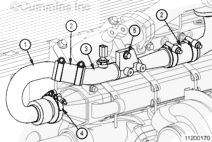
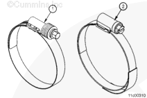
Install a hose (2) onto each end of upper EGR connection tube (3).

Slide two hose clamps loosely over both hoses.

Install the upper EGR connection tube (3) with the hoses onto the engine and install one end of the hose (2) onto the EGR mixer inlet.

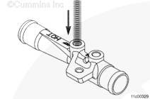
Hand start the capscrew (5) on the bracket.

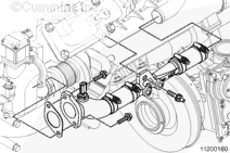
Slide one end of the EGR connection tube (1) into the other end of the hose (2).

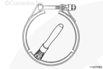
Slide the v-band clamps (4) over the EGR cooler connection.

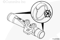
Align the v-band clamp (4) over the connection and finger tighten only (do not torque)

Tighten the upper EGR connection tube mounting capscrew (5).

Torque Value:  47  n.m  [35 ft-lb]

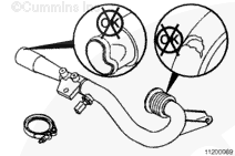
Rotate and adjust the EGR connection tube (1) so the hose (2) is straight between the ends of the EGR connection tubes (1) and (3).

Tighten the v-band clamp (4).

Torque Value:  17  n.m  [150 in-lb]

SMALL | MEDIUM | LARGE


Position the hose evenly between the hose stops (if available) on the EGR connection tubes (1 and 3).

Position the hose clamps loosely and evenly between the hose bead (if available) and the edge of the hose or 16 mm [5/8 in] from the edge of the hoses.

Tighten the hose clamps.

Breeze Clamps (1):

Torque Value:  7  n.m  [62 in-lb]

Norma Clamps (2):

Torque Value:  5  n.m  [44 in-lb]

Position the hose evenly between the EGR connection tube and the EGR mixer inlet.

Position the hose clamps loosely and evenly between the hose bead and the end of the hose.

Tighten the hose clamps.

Breeze Clamps (1):

Torque Value:  7  n.m  [62 in-lb]

Norma Clamps (2):

Torque Value:  5  n.m  [44 in-lb]
 
SMALL | MEDIUM | LARGE
   

Automotive with CM876


Remove the protective caps and heavy tape.

Install the differential pressure sensing tubes onto the EGR venturi tube and the EGR differential pressure sensor adapter, but do not torque. Refer to Procedure 011-026 in Section 11.

Install and tighten the EGR venturi tube mounting stud.

Torque Value:  47  n.m  [35 ft-lb]
 
SMALL | MEDIUM | LARGE


Position the rear hose evenly between the EGR connection and EGR venturi tube. Position the front hose evenly between the EGR venturi tube and the EGR mixer inlet.

Tighten the EGR connection hose clamps.

Breeze Clamps (1):

Torque Value:  7  n.m  [62 in-lb]

Norma Clamps (2):

Torque Value:  5  n.m  [44 in-lb]
 
SMALL | MEDIUM | LARGE
   

Finishing Steps

TOC

  • Install the differential pressure sensor tubes to the EGR connection tube. Refer to Procedure 011-026 in Section 11.
  • Disconnect engine wiring harness from the exhaust temperature sensor. For ISM engines, see the following procedure in the Troubleshooting and Repair Manual, CM870 Electronic Control System ISM Engines, Bulletin 4021381. Refer to Procedure 019-043,in Section 19.
  • Operate the engine and check for leaks.

SMALL | MEDIUM | LARGE
Last Modified:  29-Apr-2009