Do not remove the pressure cap from a hot engine. Wait until the coolant temperature is below 50°C [120°F] before removing the pressure cap. Heated coolant spray or steam can cause personal injury.
WARNING
Coolant is toxic. Keep away from children and pets. If not reused, dispose of in accordance with local environmental regulations.
CAUTION
Make sure that electrical power is removed from exhaust gas recirculation (EGR) valve before disconnecting the motor and position sensor connectors from the engine harness. The EGR valve can be damaged.
CAUTION
Do not apply 12-VDC directly to the EGR valve motor. Damage will result to the EGR valve.
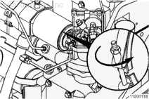
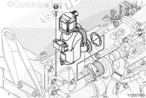
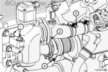
Disconnect the EGR valve motor controller connector.
Disconnect the EGR valve position sensor connector. For the ISM engine, see the following procedure in the Troubleshooting and Repair Manual, CM870 Electronic Control System, ISM Engines, Bulletin 4021381. Refer to Procedure 019-372 in Section 19.
Make sure that electrical power is removed from exhaust gas recirculation (EGR) valve before disconnecting the motor connector from the engine harness. The EGR valve can be damaged.
NOTE: Brush away any loose dirt from the vicinity of the air handling connections to avoid contamination of the interior of the engine.
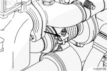
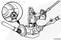
Disconnect the EGR valve actuator connector.
Disconnect the EGR temperature sensor. For ISX engines, see the following procedure in the Troubleshooting and Repair Manual ISX CM871 and ISM CM876 Electronic Control System, Bulletin 4021560. Refer to Procedure 019-378 in Section 19.
When using solvents, acids, or alkaline materials for cleaning, follow the manufacturer’s recommendations for use. Wear goggles and protective clothing to reduce the possibility of personal injury.
WARNING
Wear appropriate eye and face protection when using compressed air. Flying debris and dirt can cause personal injury.
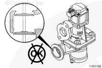
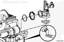
Check to be sure the EGR poppet head is present. If the poppet head is missing, run a stiff wire through every port of the exhaust manifold to locate the missing poppet head.
Do not assemble the engine without finding the missing poppet head.
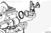
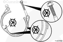
Clean the mounting surfaces with a shop towel wetted with safety solvent to remove any deposits or debris.
Dry with compressed air.
Inspect the mounting surfaces for cracks, fretting, or other damage.
Inspect the EGR valve motor and position sensor for damage.
When using solvents, acids, or alkaline materials for cleaning, follow the manufacturer’s recommendations for use. Wear goggles and protective clothing to reduce the possibility of personal injury.
WARNING
Wear appropriate eye and face protection when using compressed air. Flying debris and dirt can cause personal injury.
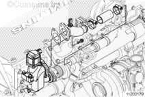
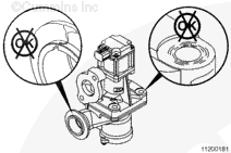
Clean the EGR valve mounting and sealing surfaces with a shop towel wetted with safety solvent to remove any deposits or debris.
Dry with compressed air.
Inspect the mounting surfaces for cracks, fretting, or any other damage.
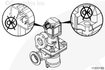
Inspect the EGR valve poppets for a stuck open condition. If the EGR valve is stuck open, replace the EGR valve. Do not try to pry the valve poppets open or closed.
Inspect the EGR valve actuator for cracks or any other damage. Replace if damage is found.
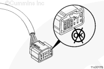
Inspect the EGR valve actuator connector for corrosion, worn pins, or any other damage. Replace the EGR valve assembly if corrosion, worn pins, or any other damage is found.
After inspection of component, cover all open points with protective caps from the Air Handling Clean Care Kit or with heavy tape, if needed.
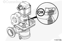
Soot leakage at the EGR valve weep hole is normal and can be expected. Do not replace the EGR valve if soot streaks are found at the EGR valve weep hole.
After cleaning and inspection of the component, cover all open points with protective caps from the Air Handling Clean Care Kit or with heavy tape, if needed.
Connect the EGR valve position sensor connector. For ISM engines, see the following procedure in the Troubleshooting and Repair Manual, CM870 Electronic Control System, ISM Engines, Bulletin 4021381. Refer to Procedure 019-372 in Section 19.
Connect the EGR temperature sensor. For ISX and ISM engines, see the following procedure in the Troubleshooting and Repair Manual CM871 and CM876 Electronic Control System ISX and ISM Engines, Bulletin 4021560. Refer to Procedure 019-378 in Section 19.
Connect the EGR valve actuator connector.
Start and operate the engine and check for exhaust or coolant leaks.
If the damaged component resulted in coolant, oil, excessive fuel or excessive black smoke entering the exhaust system, the aftertreatment system must be inspected. Refer to Procedure 014-013 in Section 14.
Hello, I'm Jack, a diesel engine fan and a blogger. I write about how to fix and improve diesel engines, from cars to trucks to generators. I also review the newest models and innovations in the diesel market. If you are interested in learning more about diesel engines, check out my blog and leave your feedback.
View all posts by Jack
 WARNING
  CAUTION


;)
;)
;)
;)
;)
;)
;)
;)
;)
;)
;)
;)
;)
;)
;)
;)
;)
;)
;)
;)
;)
;)
;)
;)
;)
;)
;)
;)
;)
;)
;)
;)
;)
;)
;)
;)