NOTE: Removal of the sensor plumbing does not require the sensor to be removed. Remove the sensor only if the sensor adapter is being replaced. To remove the sensor refer to Procedure 019-376 in the Troubleshooting and Repair Manual, CM870 Electronic Control System ISM Engines, Bulletin 4021381.
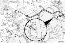
Remove the p-clip and the mounting capscrew.
Loosen the tube nuts at the exhaust manifold and at the sensor adapter.
When using solvents, acids, or alkaline materials for cleaning, follow the manufacturer’s recommendations for use. Wear goggles and protective clothing to reduce the possibility of personal injury.
WARNING
Wear appropriate eye and face protection when using compressed air. Flying debris and dirt can cause personal injury.
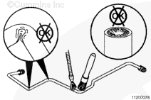
Check the inside of the tube. If clogged, use compressed air to remove debris or soot buildup.
Clean the outside of the tube with safety solvent.
Remove the sensor adapter mounting screws so that the adapter can float to help the tube nut thread start properly.
Apply a film of high temperature anti-sieze compound to the threads of the nuts.
Position the exhaust gas pressure sensing tube as illustrated in the graphic.
Pre-start the tube nuts into the respective threaded bosses.
Tighten the tube nuts.
Torque Value: 16 n.m [144 in-lb]
Attach the p-clip to the tube with the loop facing outward and down.
Pre-start the capscrew through the clip and the cooler bracket, into the air intake manifold.
Tighten the capscrew.
Torque Value: 47 n.m [35 ft-lb]
If malfunction resulted in coolant, oil, excessive fuel or excessive black smoke in the exhaust system, the aftertreatment system must be inspected. Refer to Procedure 014-013.
Hello, I'm Jack, a diesel engine fan and a blogger. I write about how to fix and improve diesel engines, from cars to trucks to generators. I also review the newest models and innovations in the diesel market. If you are interested in learning more about diesel engines, check out my blog and leave your feedback.
View all posts by Jack

 WARNING


;)
;)
;)
;)