NOTE: Use the steps found in the Clean and Inspect for Reuse section to clean the EGR cooler.
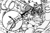
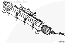
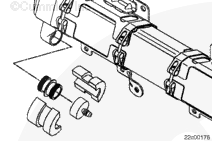
Make sure the air pressure regulator is closed, and connect compressed air to the pressure regulator.
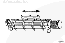
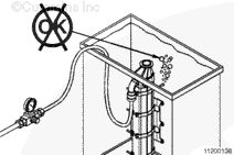
Completely submerge the EGR cooler in room temperature water. Make sure to submerge the cooler vertically, with the EGR cooler connection down, so that air can not be left in the open (gas) side of the cooler.
Apply 206 kPa [30 psi] of air pressure to the cooler.
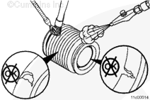
Inspect for bubbles escaping from uncapped gas ports of the EGR cooler.
NOTE: Bubbles coming from a damaged EGR cooler will be very small or will not be a steady stream.
Verify that bubbles are not a result of loose fittings or trapped air.
If bubbles are not observed, the EGR cooler is reusable.
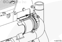
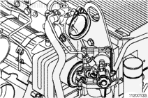
If the EGR cooler is not usable, inspect the turbocharger turbine housing and EGR valve inlet for any signs of coolant deposits. Coolant deposits can be identified as dried white deposits coating the inside of the turbine housing.
If the EGR cooler is not reusable, replace the crankcase breather element. Refer to Procedure 003-019 in Section 3.
If coolant deposits are found, inspect the turbocharger for progressive damage. Coolant can cause the turbocharger to stick. Use the following procedure for inspection guideines. Refer to Procedure 010-033 in Section 10.
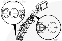
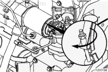
If coolant deposits are found in the EGR valve, inspect the EGR valve for progressive damage.
Coolant can cause the EGR valve to stick and allow the coolant to collect.
Remove the EGR valve and inspect for reuse. Refer to Procedure 011-022 in Section 11.
|
 WARNING


 CAUTION
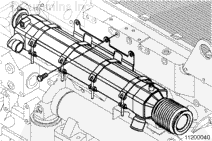


;)
;)
;)
;)
;)
;)
;)
;)
;)
;)
;)
;)
;)
;)
;)
;)
;)
;)
;)
;)
;)
;)
;)
;)
;)
;)
;)
;)
;)
;)
;)
;)
;)
;)
;)
;)
;)
;)
;)
;)