ISM, ISMe, and QSM11 – 011-007   Exhaust Manifold, Dry

Initial Check

TOC

With CM870 and CM570


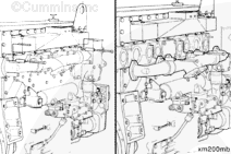
Operate the engine and inspect the exhaust manifold for leaks at the slip joints.

If the manifold is leaking at the slip joints, it must be repaired.

Some ISM engines are equipped with exhaust seal rings located within the slip joints. All ISM CM876 engines are equipped with exhaust seal rings.

NOTE: For engines not equipped with seal rings – the kit for the front slip joint is different than the kit for the rear slip joint. The outer shells are different, as well as the graphite seal. Only the clamps are similar.

SMALL | MEDIUM | LARGE

Repair

TOC

Automotive with CM875, CM870 and CM570


 WARNING 

To reduce the possibility of personal injury from hot surfaces, allow the engine to cool before beginning work. Wear appropriate hand and eye protection.

NOTE: For engines without exhaust seal rings.

Exhaust Manifold Slip Joint Seal Kit Contents
Part Description
Quantity per Kit
Covers
2
Seal
1
Clamp
1
Note: Each kit contains parts for one slip joint repair. Two kits, front and rear, will be needed to service the front and back.

Remove the turbocharger inlet and exhaust piping. Refer to Procedure 010-033 in Section 10.

Remove the front and rear exhaust manifold heat shields located below the manifold. Refer to Procedure 011-032 in Section 11.

SMALL | MEDIUM | LARGE


Twist the graphite seal to open it, and place it on the end section of the manifold, up against the slip joint.

SMALL | MEDIUM | LARGE


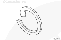
NOTE: The recessed inside diameter goes against the center section. The split in the seal is located horizontally away from the engine.

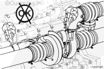
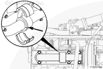
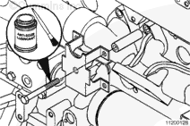
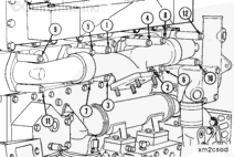
Place the top and bottom shells over the graphite ring and the exhaust housing center section step.

When placing the shells over the seal, start with the back edges closer together than the front. When the clamp is tightened it will pull the graphite split tighter together.

SMALL | MEDIUM | LARGE


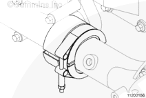
Place the top and bottom shells over the slip joint and graphite seal with the notch in the cover toward the center of the exhaust manifold center section.

NOTE: A pry bar can be used to get the outer shells pressed together enough to get the clamp on. Do not damage the EGR cooler with the pry bar.

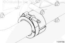
Be sure to keep the mating edges aligned with the exhaust manifold parting line.

SMALL | MEDIUM | LARGE


Front Seal – Note the location and orientation of the clamp.

Tighten the clamp.

Torque Value:  11  n.m  [97 in-lb]

SMALL | MEDIUM | LARGE


Rear Seal – Note the location and orientation of the clamp.

Tighten the clamp.

Torque Value:  11  n.m  [97 in-lb]

Replace the heat shields. Refer to Procedure 011-032 in Section 11.

Replace the turbocharger plumbing.

Clean the soot from around the slip joint area.

SMALL | MEDIUM | LARGE
   

Preparatory Steps

TOC

Automotive with CM870


 WARNING 

Coolant is toxic. Keep away from children and pets. If not reused, dispose of in accordance with local environmental regulations.
 WARNING 

Do not remove the pressure cap from a hot engine. Wait until the coolant temperature is below 50°C [120°F] before removing the pressure cap. Heated coolant spray or steam can cause personal injury.

SMALL | MEDIUM | LARGE
   

Automotive with CM876


NOTE: Brush away any loose dirt from the vicinity of the air handling connections to avoid contamination of the interior of the engine.

  1. Drain the coolant. Refer to Procedure 008-018 in Section 8.
  2. Remove the air piping from the turbocharger. Cover open points using caps from the Air Handling and Vehicle Air Plumbing Clean Care Kits.
  3. Remove the turbocharger. Refer to Procedure 010-033 in Section 10.
  4. Remove the water manifold return tube. Refer to Procedure 008-061 in Section 8.
  5. Remove the EGR cooler coolant lines. Refer to Procedure 011-031 in Section 11.
  6. Remove the exhaust gas pressure sensor tube. Refer to Procedure 011-027 in Section 11.

SMALL | MEDIUM | LARGE
   

Automotive with CM570


  1. Remove the air piping from the turbocharger.
  2. Remove the turbocharger. Refer to Procedure 010-033 in Section 10.

SMALL | MEDIUM | LARGE
   

Remove

TOC

Remove the EGR cooler coolant return tube bracket from the exhaust manifold.

Remove the exhaust manifold.

Cover all open points on the exhaust manifold and cylinder head with the appropriate protective caps and heavy tape if needed.

Remove the two upper capscrews from the end sections of the exhaust manifold and install two guide studs, Part Number 3376488.

Remove the remaining capscrews, exhaust manifold, and discard the gaskets.

SMALL | MEDIUM | LARGE
   

Automotive with CM570


Remove the two upper capscrews from the end sections of the exhaust manifold and install two guide studs, Part Number 3376488.

Remove the remaining capscrews, exhaust manifold, and discard the gaskets.

SMALL | MEDIUM | LARGE
   

Disassemble

TOC

Remove the exhaust manifold end sections.

SMALL | MEDIUM | LARGE


Cover the open points of the exhaust manifold with the appropriate protective caps or heavy tape, if needed.

SMALL | MEDIUM | LARGE
   

Clean and Inspect for Reuse

TOC

Automotive with CM875, CM870 and CM570


 WARNING 

When using a steam cleaner, wear safety glasses or a face shield, as well as protective clothing. Hot steam can cause serious personal injury.
 WARNING 

Wear appropriate eye and face protection when using compressed air. Flying debris and dirt can cause personal injury.

Use 240-grit emery cloth to remove carbon deposits from the sealing surfaces.

Use steam to clean the exhaust manifold.

Dry with compressed air.

SMALL | MEDIUM | LARGE


Inspect the parts for cracks or other damage.

A charge air cooler failure can cause progressive damage to the exhaust manifold. If the exhaust manifold is damaged, check the charge air cooler. Refer to Procedure 010-027 in Section 10.

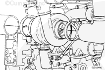
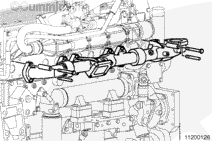
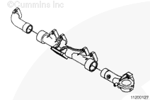
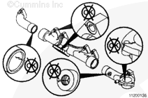
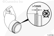
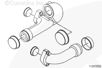
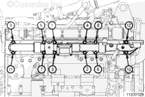
Inspect the exhaust manifold slip joint for wear.

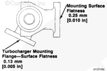
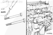
Inspect the exhaust manifold turbocharger mounting surface for warping.

SMALL | MEDIUM | LARGE


Inspect the mounting surfaces for flatness.

The exhaust manifold mounting surface must be flat to within 0.25 mm [0.010 in]. The turbocharger mounting flange must have a surface flatness of 0.13 mm [0.005 in].

If these surfaces are not within the flatness specifications, see the Alternative Repair Manual, L10 and M11 Series Engines, Bulletin 3810310.

SMALL | MEDIUM | LARGE
   

Automotive with CM876


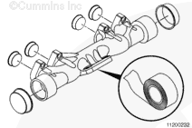
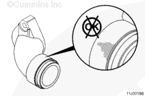
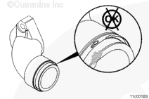
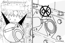
Inspect the exhaust manifold slip joints for signs of soot leakage.

If there is no evidence of an exhaust leak from the slip joints and there are no visible cracks or damage, do not remove the exhaust manifold end sections.

SMALL | MEDIUM | LARGE


Inspect the exhaust manifold turbocharger mounting flange for warpage.

The exhaust manifold mounting surface must be flat to within 0.24 mm [0.010 in].

The turbocharger mounting flange must have a surface flatness of 0.13 mm [0.005 in].

SMALL | MEDIUM | LARGE


Inspect for cracks or other damage.

NOTE: A charge air cooler failure can cause progressive damage to the exhaust manifold. If the exhaust manifold is damaged, check the charge air cooler. Refer to Procedure 010-027 in Section 10.

SMALL | MEDIUM | LARGE


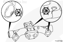
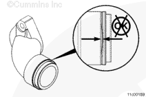
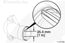
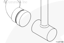
Check that the exhaust seal is fully seated against the shoulder of the exhaust manifold male end section. If the exhaust seal is not fully seated against the shoulder, the exhaust seal must be replaced.

SMALL | MEDIUM | LARGE


Inspect the manifold seal bore for wear.

Inspect the exhaust seal for signs of damage or excessive wear.

The exhaust seal must not show signs of dents or other signs of damage.

Measure the wear width on the exhaust seal ring. The wear width must not be more than 1 mm [0.04 inch] wide anywhere on the seal.

SMALL | MEDIUM | LARGE


Wear width larger than 1 mm [0.04 in] indicates a failure and the exhaust seal must be replaced.

 
SMALL | MEDIUM | LARGE


The wear width must be uniform around the seal. If one side of the exhaust seal ring is worn more than the other, the exhaust seal must be replaced.

SMALL | MEDIUM | LARGE


If there is no evidence of an exhaust leak from the slip joints and there are no visible cracks or other damage, do not remove the exhaust manifold seal rings.

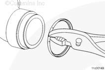
If there is a failure or damage, remove the exhaust manifold seal rings.

SMALL | MEDIUM | LARGE


Remove the exhaust seal rings, located within the slip-joint.

Use tin snip or side cuts, to cut halfway through the seal in two locations, about 25.4 mm [1 in] apart.

SMALL | MEDIUM | LARGE


Twist and pull the seal off of the exhaust manifold end sections.

Take care not to damage the seal carrier surface.

Discard the exhaust seal ring.

SMALL | MEDIUM | LARGE


Use a soft cloth or a shop towel wetted with a safety solvent to remove carbon deposits from the sealing surfaces.

SMALL | MEDIUM | LARGE


Inspect the exhaust seal ring mating surfaces of the male and female sections of the exhaust manifolds.

If scratches or nicks can be felt with a fingernail on the exhaust seal ring mating surfaces, the exhaust manifold section must be replaced.

SMALL | MEDIUM | LARGE


After completing inspections, cover the exhaust manifold with the appropriate protective caps or heavy tape if needed.

SMALL | MEDIUM | LARGE
   

Assemble

TOC

Automotive with CM875, CM870 and CM570


Install the exhaust manifold end sections to the center section.

SMALL | MEDIUM | LARGE
   

Automotive with CM876


Install the exhaust manifold end sections to the center section.

The end section bolt holes must be 225 mm [8.875 inch] center to center before installing onto the cylinder head.

NOTE: The exhaust manifold sections must be assembled on a flat surface for proper alignment.

SMALL | MEDIUM | LARGE


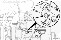
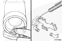
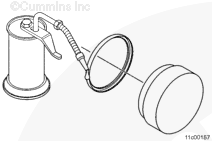
Place the exhaust seal onto the lip of the exhaust seal installer, Part Number 4918709.

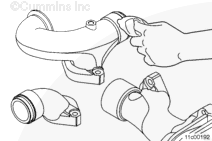
Use a light coat of grease or clean engine oil to lubricate the exhaust seal during assembly onto the male and female sections of the exhaust manifold.

 
SMALL | MEDIUM | LARGE


Position the seal installer and seal in line with the sealing surface on the exhaust manifold and strike with a lead or a dead blow hammer until the seal is fully seated.

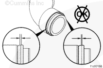
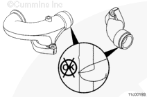
Seal rings must remain square to manifold component axes during installation.

SMALL | MEDIUM | LARGE
   

Install

TOC

Remove any protective caps or heavy tape.

Install two guide studs, Part Number 3376488, in the two top end holes of the cylinder head exhaust ports.

Install new gaskets between the cylinder head and the exhaust manifold.

Install the exhaust manifold over the guide pins.

SMALL | MEDIUM | LARGE


Attach the EGR cooler coolant return tube bracket at the number 4 and number 5 exhaust ports. Orient bracket as shown.

Apply a film of high temperature anti-seize compound to the capscrew threads to ensure proper loading on capscrews.

Hand start the capscrews through the bracket, spacers, manifold, and gaskets.

SMALL | MEDIUM | LARGE


Apply a film of high temperature anti-seize compound to the capscrew threads and install them into the cylinder head.

Remove the guide studs and install the remaining capscrews.

Tighten the capscrews in the sequence shown.

Torque Value:  57  n.m  [42 ft-lb]

SMALL | MEDIUM | LARGE
   

Automotive with CM570


Install two guide studs, Part Number 3376488, in the two top end holes of the cylinder head exhaust ports.

Install a new gasket over each guide stud.

Do not use any kind of adhesive to hold the gaskets.

SMALL | MEDIUM | LARGE


To aid in future capscrew removal, apply a coating of high temperature anti-seize compound to the capscrew threads.

Install the exhaust manifold, tubular spacers, and capscrews.

The exhaust manifold can be tilted back enough to install a new gasket on each exhaust port as the capscrews are being installed.

SMALL | MEDIUM | LARGE


Tighten the capscrews in the sequence shown.

The torque values given have been established using anti-seize compound as a lubricant.

Torque Value:

  1. 27 n.m   
    [239 in-lb]
  2. 47 n.m   
    [35 ft-lb]

SMALL | MEDIUM | LARGE
   

Finishing Steps

TOC

Automotive with CM570


Install the turbocharger. Refer to Procedure 010-033 in Section 10.

Install the air piping to the turbocharger. Refer to the OEM service manual for the correct torque value.

Fill the cooling system. Refer to Procedure 008-018 in Section 8.

Operate the engine and check for air or exhaust leaks.

SMALL | MEDIUM | LARGE
   

Automotive with CM875, CM870 and CM570


SMALL | MEDIUM | LARGE
   

Automotive with CM876


SMALL | MEDIUM | LARGE
Last Modified:  29-Apr-2009