ISM, ISMe, and QSM11 – 003-013   Rocker Lever Housing

Preparatory Steps

TOC

SMALL | MEDIUM | LARGE

Remove

TOC

Rotate the rocker levers up.

Mark the position of the crossheads as they are removed. They must be installed in the same position as from which they were removed.

Remove the crossheads to prevent them from falling into the lower area of the engine.

SMALL | MEDIUM | LARGE


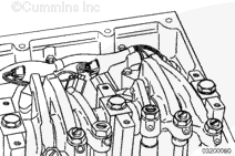
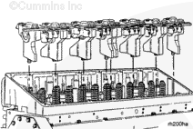
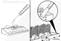
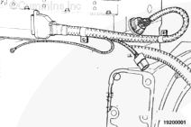
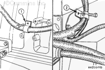
The internal engine harness is located inside the rocker housing.

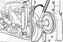
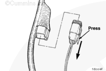
A pass through connector joins the internal and external engine harness. This connector has two clips that can manually be opened to allow separation of the two harnesses. Engines with pass through connectors in the front of the engine have clips on the outside, engines with pass through connections in the rear of the engine have clips on the inside of the rocker housing that require the valve cover to be removed to access.

SMALL | MEDIUM | LARGE


Disconnect the ground wire connection of the actuator harness (1) from the engine.

Tag the end for future identification.

Remove the external section of the actuator harness.

Use care not to damage the plug as it is being removed from the rocker housing.

SMALL | MEDIUM | LARGE


Remove the internal engine harness holding clamp capscrews.

SMALL | MEDIUM | LARGE


Separate the Deutsch 2-pin connectors from the internal engine harness to the fuel injectors.

SMALL | MEDIUM | LARGE


Remove the internal engine harness from the engine.

SMALL | MEDIUM | LARGE


Remove the rocker lever assemblies. Refer to Procedure 003-009 in Section 3.

SMALL | MEDIUM | LARGE


Remove the injectors. Refer to Procedure 006-026 in Section 6.

SMALL | MEDIUM | LARGE


Remove the rocker housing mounting capscrews.

Remove the rocker housing and the intake manifold as a complete unit.

NOTE: If high blowby is a symptom, the rocker housing gasket must be inspected before it is removed from the cylinder head.

SMALL | MEDIUM | LARGE
   

Clean and Inspect for Reuse

TOC

 WARNING 

When using a steam cleaner, wear safety glasses or a face shield as well as protective clothing. Hot steam can cause serious personal injury.
 WARNING 

Wear appropriate eye and face protection when using compressed air. Flying debris and dirt can cause personal injury.

Use steam to clean the rocker lever housing. Dry with compressed air.

Clean the cylinder head gasket surface.

SMALL | MEDIUM | LARGE


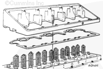
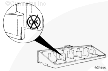
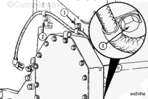
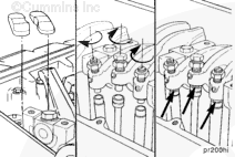
Inspect the rocker housing gasket for cuts or damage on the portion of the gasket that seals around the intake ports. Damage to the gasket can cause high blowby.

Inspect the housing for cracks or damage.

If the housing is cracked, it must be replaced.

SMALL | MEDIUM | LARGE
   

Install

TOC

Use a new gasket, and install the rocker lever housing.

SMALL | MEDIUM | LARGE


Step 1: Snug all bolts.

Step 2: Tighten the 24 capscrews in the sequence shown.

Torque Value:  34  n.m  [25 ft-lb]

Step 3: Tighten the 24 capscrews in the sequence shown.

Torque Value:  61  n.m  [45 ft-lb]

SMALL | MEDIUM | LARGE


Install the injectors. Refer to Procedure 006-026 in Section 6.

SMALL | MEDIUM | LARGE


Install the rocker lever assemblies. Refer to Procedure 003-009 in Section 3.

SMALL | MEDIUM | LARGE


Install the internal engine wiring harness on the engine.

The harness and connectors must be clear of any moving parts, so the wires will not be damaged during engine operation.

SMALL | MEDIUM | LARGE


Connect the 15-pin connector of the internal engine harness to the 15-pin connector of the external engine harness.

NOTE: The internal and external Metri-Pack connectors are “keyed.” Make sure both connectors are correctly aligned when they are joined together.

SMALL | MEDIUM | LARGE


Install the holding clamps for the internal engine harness. Tighten the capscrews.

Torque Value:  20  n.m  [15 ft-lb]

SMALL | MEDIUM | LARGE


Connect the Deutsch 2-pin connectors from the internal engine harness to the fuel injectors.

SMALL | MEDIUM | LARGE


Install the harness wire bracket to the cylinder block at points (1) and (2).

Install two mounting capscrews and tighten.

Torque Value:  41  n.m  [30 ft-lb]

SMALL | MEDIUM | LARGE


Install the external actuator harness on the engine.

Install the harness holding clamps to the support bracket and to the rear of the engine block.

Tighten the capscrew.

Torque Value:  20  n.m  [15 ft-lb]

SMALL | MEDIUM | LARGE


Install the oil temperature sensor (1) and the oil pressure sensor (2) to the cylinder block.

Torque Value:

Temperature Sensor

  1. 34 n.m   
    [25 ft-lb]
Torque Value:

Pressure Sensor

  1. 30 n.m   
    [25 ft-lb]

Install the engine position sensor (3) to the rear of the gear housing.

Torque Value:

  1. 34 n.m   
    [25 ft-lb]

SMALL | MEDIUM | LARGE


Install the sensor wire harness.

Use wire clamps to fasten the coolant temperature sensor lead to the gear housing (1), and to the front of the rocker lever housing (2) and (3).

SMALL | MEDIUM | LARGE


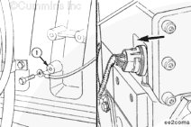
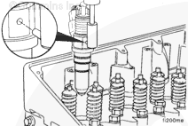
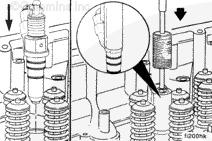
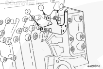
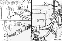
Install a wire clamp around the sensor harness and actuator fuel shutoff solenoid wire, and fastern the clamp to the cylinder block at point (1).

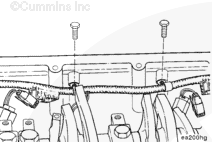
Install another wire clamp arond the intake temperature and boost pressure sensor wires and actuator harness, and fasten them to the camshaft rear cover plate (2).

SMALL | MEDIUM | LARGE


NOTE: Care must be used when matching connectors with sensors. Each sensor has its own unique connection.

NOTE: Connect the correct sensor harness wire connectors to thre following sensors:

  • Oil temperature sensor (1)
  • Oil pressure sensor (2)
  • Engine position sensor (3).

Connect the sensor and actuator harnesses together with Weather Pack connector (4).

SMALL | MEDIUM | LARGE


Install the crossheads in the same position they were removed from, and rotate the rocker levers down.

SMALL | MEDIUM | LARGE
   

Finishing Steps

TOC

SMALL | MEDIUM | LARGE
Last Modified:  21-Jan-2009