Install
TOC
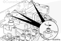
Loosen the locknuts on the secondary pistons.
Make sure the secondary pistons are fully retracted.
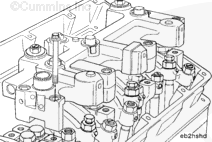
Install the rear engine brake housing on the rear rocker lever supports.
Use clean 15W-40 oil to coat the threads and the bottom side of the capscrew head.
NOTE : Washers are not used with the capscrews.
Install the capscrews in the rocker lever supports.
Do not tighten the capscrews.
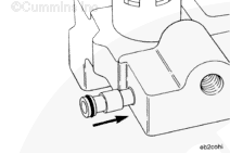
Use clean 15W-40 oil to lubricate the o-rings.
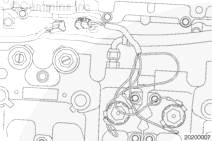
Press the connector all the way into the front housing by hand.
When installing the front housing, be sure the oil connector and o-ring are in a position to be pushed into the rear housing.
Install the front engine brake housing on the front rocker lever supports.
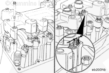
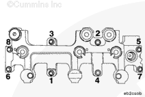
Center the oil connector between the front and rear housings before tightening the capscrews.
Tighten the capscrews in the sequence shown.
Torque Value: 81 n.m [60 ft-lb]
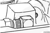
Install the internal oil connector supply hose, and tighten the capscrews.
Torque Value: 19 n.m [168 in-lb]
Install the external oil connector supply hose, and tighten the capscrews.
Torque Value: 19 n.m [168 in-lb]
Adjust
TOC
CAUTION
Do not tighten the adjusting screw too tightly. The engine can be damaged.
CAUTION
Failure to have the correct clearance can damage the engine.
To obtain maximum brake operating efficiency, and prevent engine damage by piston-to-valve contact, complete the following instructions carefully.
Adjust the exhaust valves on the appropriate cylinder. Refer to Procedure 003-004 in Section 3.
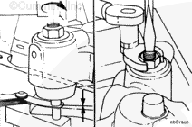
After adjusting the exhaust valves on the appropriate cylinder, insert the correct feeler gauge.
Turn the secondary piston adjusting screw down until it touches the feeler gauge.
Measurements
mm
in
Clearance for the CM570, CM870 and CM570, and CM875
0.38
0.015
Measurements
mm
in
Clearance for the CM876
0.69
0.027
Hold the screw in position, and tighten the locknut.
Torque Value:
Without the Torque Wrench Adapter
34 n.m
Torque Value:
With the Torque Wrench Adapter Part Number 3163196
30 n.m
After the secondary piston adjusting screw locknut is tightened to the correct torque value, check the clearance with the feeler gauge again.
Last Modified: 26-Feb-2009
Published by Jack
Hello, I'm Jack, a diesel engine fan and a blogger. I write about how to fix and improve diesel engines, from cars to trucks to generators. I also review the newest models and innovations in the diesel market. If you are interested in learning more about diesel engines, check out my blog and leave your feedback.
View all posts by Jack


 CAUTION

;)
;)
;)
;)
;)
;)
;)
;)
;)
;)
;)
;)
;)
;)
;)
;)
;)
;)