General Information
|
TOC |
|
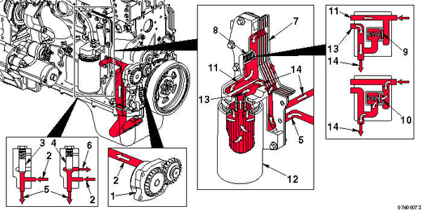
- Gerotor lubricating oil pump
- From lubricating oil pump
- Pressure regulating valve closed
- Pressure regulating valve open
- To lubricating oil cooler
- To lubricating oil pump supply
- Lubricating oil cooler
- Filter bypass valve
- Filter bypass valve closed
- Filter bypass valve open
- To lubricating oil filter
- Full-flow lubricating oil filter
- From lubricating oil filter
- Main lubricating oil rifle.
|
|
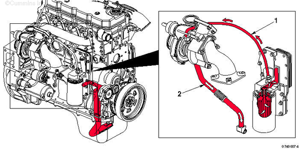
| Lubrication for the Turbocharger |
- Turbocharger lubricating oil supply
- Turbocharger lubricating oil drain.
|
|
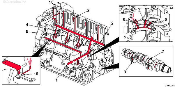
| Lubrication for the Power Components |
- From lubricating oil cooler
- Main lubricating oil rifle
- To valve train
- From main lubricating oil rifle
- To piston-cooling nozzle
- To camshaft
- Crankshaft main journal
- Oil supply to rod bearings
- Directed piston-cooling nozzle
- To internal lubrication of air compressor.
|
|
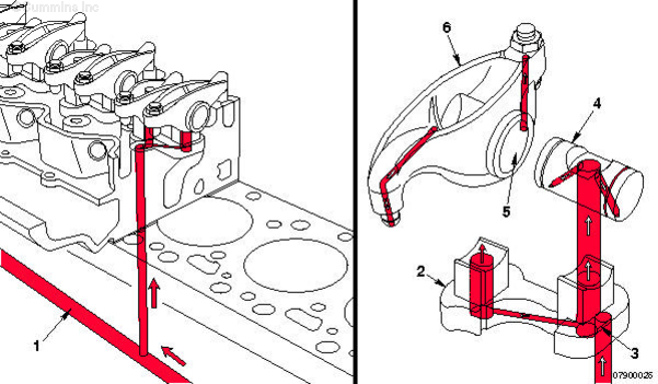
| Lubrication for the Overhead Components |
- Main lubricating oil rifle
- Rocker lever support
- Transfer slot
- Rocker lever shaft
- Rocker lever bore
- Rocker lever.
|
|
| Lubrication for the Accessory Drive |
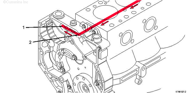
- Oil feed from block
- Oil supply to accessory drive.
NOTE: Oil returns to pan through the gear housing.
|
Last Modified: 31-Oct-2005
Published by Jack
Hello, I'm Jack, a diesel engine fan and a blogger. I write about how to fix and improve diesel engines, from cars to trucks to generators. I also review the newest models and innovations in the diesel market. If you are interested in learning more about diesel engines, check out my blog and leave your feedback.
View all posts by Jack
;)
;)
;)
;)
;)
;)
;)
;)
;)
;)