View Related Topic
Flow Diagram
|
TOC |
Without EGR
|
|
| Automotive and Industrial without EGR |
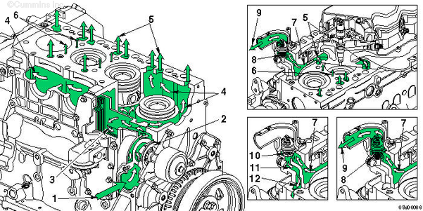
- Coolant inlet
- Pump impeller
- Coolant flow past lubricating oil cooler
- Coolant flow past cylinders
- Coolant flow from cylinder block to cylinder head
- Coolant flow between cylinders (engines
without EGR
only)
- Coolant flow to thermostat housing
- Coolant bypass passage
- Coolant flow back to radiator
- Bypass open
- Coolant bypass in cylinder head
- Coolant flow to water pump inlet.
With EGR
|
|
| Automotive Engines with EGR |
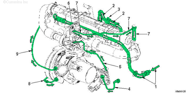
- Coolant flow from cylinder block to EGR cooler inlet
- Coolant flow from EGR cooler returning back to cylinder head
- Vent plug used for cooling system fill
- Coolant flow from cylinder block to VGT actuator inlet
- Coolant flow from VGT actuator to EGR valve inlet
- M10 vented banjo – vent orifice to surge tank
- Coolant flow return from EGR valve back to cylinder head
- Coolant flow from cylinder block to turbocharger bearing housing
- Coolant flow return from turbocharger bearing housing back to the rear of the cylinder head.
|
Last Modified: 21-Jun-2006
Published by Jack
Hello, I'm Jack, a diesel engine fan and a blogger. I write about how to fix and improve diesel engines, from cars to trucks to generators. I also review the newest models and innovations in the diesel market. If you are interested in learning more about diesel engines, check out my blog and leave your feedback.
View all posts by Jack
;)
;)
;)
;)