View Related Topic
Inspect for Reuse
TOC
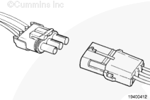
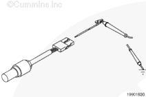
Inspect the engine harness and sensor connector pins.
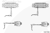
Disconnect the engine position sensor (EPS) and electronic control module (ECM) connectors.
Inspect the engine harness and engine position sensor connector pins for the following:
Loose connector
Corroded pins
Bent or broken pins
Pushed back or expanded pins
Moisture in or on the connector
Missing or damaged connector seals
Dirt or debris in or on the connector pins
Connector shell broken
Wire insulation damage
Damaged connector locking tab.
Refer to the circuit diagram or wiring diagram for connector pin identification.
For general inspection techniques, refer to Procedure 019-361 (Component Connector and Pin Inspection) in Section 19.
If any of the above conditions are found, follow the appropriate procedure below:
Repair the damaged pins
Repair or replace the engine harness, or replace the sensor, whichever has the damaged pins
Flush the dirt, debris, or moisture from the connector pins, use electronic contact cleaner, Part Number 3824510
Install the appropriate connector seal if it is damaged or missing.
Repair the engine harness.Refer to Procedure 019-220 (Augat™ Connector Series) in Section 19.
Replace the engine harness.
For B5.9G, C8.3G, and L10G-III engines, refer to Procedure 019-043 (Engine Wiring Harness) in Section 19 in Troubleshooting and Repair Manual, Fuel Systems and Electronics, B5.9G, C8.3G, and L10G-III, Bulletin 3666118.
For Gas Plus engines, refer to Procedure 019-043 (Engine Wiring Harness) in Section 19 in Troubleshooting and Repair Manual, Electronic Control System, Gas Plus Engines, Bulletin 4021317.
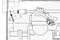
Inspect the sensor.
Disconnect the EPS and ECM connectors.
Inspect the engine position sensor for the following:
Metal debris on the end of the sensor
Damage to the end of the sensor caused by the engine gear
Oil leakage or insulation problems such as swelling
Damaged electrical potting in the sensing end of the sensor.
If any of the above conditions are found, follow the appropriate procedure below.
Replace the sensor:
For B5.9G, C8.3G, and L10G-III engines, refer to Procedure 019-038 (Engine Position Sensor (EPS)) in Section 19 in Troubleshooting and Repair Manual, Fuel Systems and Electronics, B5.9G, C8.3G, and L10G-III, Bulletin 3666118.
For Gas Plus engines, refer to Procedure 019-038 (Engine Position Sensor (EPS)) in Section 19 in Troubleshooting and Repair Manual, Electronic Control System, Gas Plus Engines, Bulletin 4021317.
Inspect the camshaft tone wheel/gear teeth for damage or spinning:
For B5.9G, B5.9LPG, B Gas Plus, B LPG Plus, B Gas International, and G5.9 engines, refer to Procedure 001-013 (Camshaft Gear (Camshaft Removed)) in Section 1 in Troubleshooting and Repair Manual, B5.9G, B5.9LPG, B Gas Plus, B LPG Plus, B Gas International, and G5.9, Bulletin 3666164.
For C8.3G, C Gas Plus, and L Gas Plus engines, refer to Procedure 001-013 (Camshaft Gear (Camshaft Removed)) in Section 1 in Troubleshooting and Repair Manual, C8.3G, C Gas Plus, and L Gas Plus Engines, Bulletin 3666206.
For L10G engines, refer to Procedure 001-013 (Camshaft Gear (Camshaft Removed)) in Section 1 in Troubleshooting and Repair Manual, L10G (Natural Gas) Engines, Bulletin 3666207.
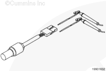
Resistance Check
TOC
Disconnect the EPS and ECM connectors.
Use a multimeter to check the resistance of the sensor.
Measure the resistance from the engine position sensor SIGNAL pin to the engine position sensor RETURN pin in the engine position sensor connector.
Measure the resistance from the engine position backup SIGNAL pin to the engine position backup RETURN pin in the engine position sensor connector.
Refer to the circuit diagram or the wiring diagram for connector pin identification.
For general resistance measurement techniques, refer to Procedure 019-360 (Resistance Measurements Using a Multimeter) in Section 19.
If the resistance isnot between 1000 and 2000 ohms, replace the sensor.
For B5.9G, C8.3G, and L10G-III engines, refer to Procedure 019-038 (Engine Position Sensor (EPS)) in Section 19 in Troubleshooting and Repair Manual, Fuel systems and Electronics, B5.9G, C8.3G, and L10G-III, Bulletin 3666118.
For Gas Plus engines, refer to Procedure 019-038 (Engine Position Sensor (EPS)) in Section 19 in Troubleshooting and Repair Manual, Electronic Control System, Gas Plus Engines, Bulletin 4021317.
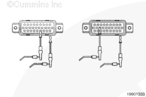
Check for an open circuit.
Disconnect the EPS and ECM connectors.
Use a multimeter to measure the resistance between pin B on the harness side of the EPS connector and pin 4 in the ECM connector.
Use a multimeter to measure the resistance between pin C on the harness side of the EPS connector and pin 17 in the ECM connector.
Refer to the circuit diagram or the wiring diagram for connector pin identification.
For general resistance measurement techniques, refer to Procedure 019-360 (Resistance Measurements Using a Multimeter) in Section 19.
If the resistance in either circuit is less than 10 ohms, repair or replace the harness.
Repair the engine harness.Refer to Procedure 019-202 (Metri-Pack™ Connector Series) in Section 19.
Replace the engine harness.
For B5.9G, C8.3G, and L10G-III engines, refer to Procedure 019-043 (Engine Wiring Harness) in Section 19 in Troubleshooting and Repair Manual, Fuel Systems and Electronics, B5.9G, C8.3G, and L10G-III, Bulletin 3666118.
For Gas Plus engines, refer to Procedure 019-043 (Engine Wiring Harness) in Section 19 in Troubleshooting and Repair Manual, Electronic Control System, Gas Plus Engines, Bulletin 4021317.
Check for Short Circuit to Ground
TOC
Disconnect the EPS and ECM connectors.
Check for a short circuit to ground.
Use a multimeter to measure the resistance from the engine position SIGNAL pin in the engine position sensor connector, sensor side, to the engine block ground.
Use a multimeter to measure the resistance from the engine position RETURN pin in the engine position sensor connector, sensor side, to the engine block ground.
Refer to the circuit diagram or the wiring diagram for connector pin identification.
For general resistance measurement techniques, refer to Procedure 019-360 (Resistance Measurements Using a Multimeter) in Section 19.
If the resistance in either circuit is less than 100k ohms, repair or replace the sensor.
Repair the sensor.Refer to Procedure 019-201 (Weather-Pack™ Connector Series) in Section 19.
Replace the sensor.
For B5.9G, C8.3G, and L10G-III engines, refer to Procedure 019-038 (Engine Position Sensor (EPS)) in Section 19 in Troubleshooting and Repair Manual, Fuel Systems and Electronics, B5.9G, C8.3G, and L10G-III, Bulletin 3666118.
For Gas Plus engines, refer to Procedure 019-038 (Engine Position Sensor (EPS)) in Section 19 in Troubleshooting and Repair Manual, Electronic Control System, Gas Plus Engines, Bulletin 4021317.
Check for Short Circuit from Pin to Pin
TOC
Disconnect the EPS and ECM connectors.
Check for a pin-to-pin short circuit.
Use a multimeter to measure the resistance between pin 4 and pin 17 to all the other pins in the ECM connector.
Refer to the circuit diagram or the wiring diagram for connector pin identification.
For general resistance measurement techniques, refer to Procedure 019-360 (Resistance Measurements Using a Multimeter) in Section 19.
If the resistance in either circuit is less than 100k ohms, repair or replace the harness.
Repair the engine harness.Refer to Procedure 019-202 (Metri-Pack™ Connector Series) in Section 19.
Replace the engine harness.
For B5.9G, C8.3G, and L10G-III engines, refer to Procedure 019-043 (Engine Wiring Harness) in Section 19 in Troubleshooting and Repair Manual, Fuel Systems and Electronics, B5.9G, C8.3G, and L10G-III, Bulletin 3666118.
For Gas Plus engines, refer to Procedure 019-043 (Engine Wiring Harness) in Section 19 in Troubleshooting and Repair Manual, Electronic Control System, Gas Plus Engines, Bulletin 4021317.
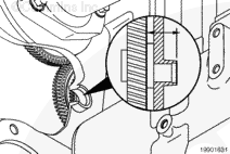
Check for adequate camshaft speed/position sensor air gap.
Remove the engine position sensor.
For B5.9G, C8.3G, and L10G-III engines, refer to Procedure 019-038 (Engine Position Sensor (EPS)) in Section 19 in Troubleshooting and Repair Manual, Fuel Systems and Electronics, B5.9G, C8.3G, and L10G-III, Bulletin 3666118.
For Gas Plus engines, refer to Procedure 019-038 (Engine Position Sensor (EPS)) in Section 19 in Troubleshooting and Repair Manual, Electronic Control System, Gas Plus Engines, Bulletin 4021317.
Measure the distance between the sensor o-ring sealing surface and the edge of the tone wheel to verify an adequate air gap.
If the air gap distance is less than 33.81 mm [1.33 in] or greater than 34.06 mm [1.34 in], then inspect the camshaft tone wheel/gear teeth for damage or spinning.
For B5.9G, B5.9LPG, B Gas Plus, B LPG Plus, B Gas International, and G5.9 engines, refer to Procedure 001-013 (Camshaft Gear (Camshaft Removed)) in Section 1 in Troubleshooting and Repair Manual, B5.9G, B5.9LPG, B Gas Plus, B LPG Plus, B Gas International, and G5.9, Bulletin 3666164.
For C8.3G, C Gas Plus, and L Gas Plus engines, refer to Procedure 001-013 (Camshaft Gear (Camshaft Removed)) in Section 1 in Troubleshooting and Repair Manual, C8.3G, C Gas Plus, and L Gas Plus Engines, Bulletin 3666206.
For L10G engines, refer to Procedure 001-013 (Camshaft Gear (Camshaft Removed)) in Section 1 in Troubleshooting and Repair Manual, L10G (Natural Gas) Engines, Bulletin 3666207.
Last Modified: 11-Aug-2008
Published by Jack
Hello, I'm Jack, a diesel engine fan and a blogger. I write about how to fix and improve diesel engines, from cars to trucks to generators. I also review the newest models and innovations in the diesel market. If you are interested in learning more about diesel engines, check out my blog and leave your feedback.
View all posts by Jack


;)
;)
;)
;)
;)
;)
;)
;)
;)
;)
;)
;)
;)
;)