|
High Mixer Inlet Pressure – Overboost
|

Overview
| CODE | REASON | EFFECT |
| Fault Code: 124 PID: P102 SPN: 102 FMI: 0/16 LAMP: Amber SRT: |
High mixer inlet pressure – Overboost. Pressure is above the engine protection limit. |
Engine power derate. |
|
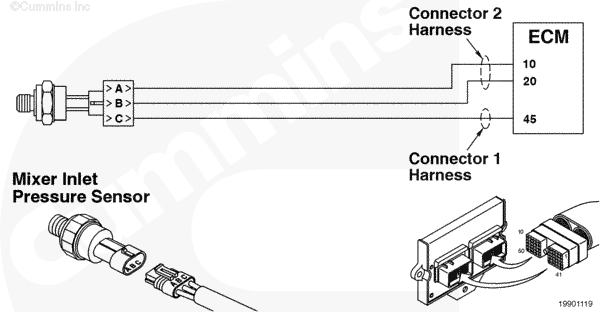
Mixer Inlet Pressure Sensor Circuit |
 |
;)
;)
Circuit Description
The Mixer Inlet Pressure Sensor measures the inlet air pressure entering the fuel housing.
Component Location
The Mixer Inlet Pressure Sensor is located in the air inlet elbow.
Shop Talk
The Mixer Inlet Pressure Sensor detects the pressure of the air entering the mixer housing. This is sometimes referred to as the boost pressure sensor or compressor outlet pressure sensor. If the Mixer Inlet Pressure Sensor is disconnected, the engine can continue operating by using the accelerator plate position and the manifold absolute pressure to estimate the mixer inlet pressure. Before performing any wiring checks, disconnect the sensor from the engine harness.
Troubleshooting Steps
| STEPS | SPECIFICATIONS | |
|---|---|---|
| STEP 1. | Check the fault codes. | |
| STEP 1A. Read the fault codes. | Fault Codes 122 or 123 active? | |
| STEP 2. | Check the Mixer Inlet Pressure Sensor. | |
| STEP 2A. Inspect the engine harness and Mixer Inlet Pressure Sensor connector pins. | No damaged pins | |
| STEP 2B. Verify the mixer inlet pressure. | Mixer inlet and manifold absolute pressure values the same at atmospheric pressure? | |
| STEP 2C. Read the fault codes. | Fault Code 124 active? | |
| STEP 3. | Check the mechanical components. | |
| STEP 3A. Check the turbocharger. | Turbocharger is correct and is operating correctly? | |
| STEP 3B. Check the air intake restriction. | Is restriction within specification? | |
| STEP 4. | Clear the fault codes. | |
| STEP 4A. Disable the fault code. | Fault Code 124 inactive? | |
| STEP 4B. Clear the inactive fault codes. | All fault codes cleared? | |
Guided Step 1 – Check the fault codes.
| Guided Step 1A – Read the fault codes. | |
|---|---|
Conditions
ActionRead the fault codes. Use INSITE™ electronic service tool to read the fault codes. |
|
|
Fault Codes 122 or 123 active? |
|
| YES | NO |
|
Troubleshoot Fault Codes 122 or 123. |
No Repair |
|
Appropriate troubleshooting tree
|
|
Guided Step 2 – Check the Mixer Inlet Pressure Sensor.
| Guided Step 2A – Inspect the engine harness and Mixer Inlet Pressure Sensor connector pins. | |
|---|---|
Conditions
ActionInspect the engine harness and mixer inlet pressure sensor connector pins for the following:
For general inspection techniques, refer to Component Connector and Pin Inspection, Procedure |
|
|
Damaged or dirty pins? |
|
| YES | NO |
|
Repair the damaged pins. Repair or replace the engine harness, or replace the sensor, whichever has the damaged pins.
|
No Repair |
| Guided Step 2B – Verify the mixer inlet pressure. | |
|---|---|
Conditions
ActionCheck the mixer inlet pressure with INSITE™ electronic service tool.
|
|
|
Mixer inlet and manifold absolute pressure values the same at atmospheric pressure? |
|
| YES | NO |
| No Repair |
Replace the Mixer Inlet Pressure Sensor. Refer to Procedure |
| Guided Step 2C – Read the fault codes. | |
|---|---|
Conditions
ActionRead the fault codes.
|
|
|
Fault Code 124 active? |
|
| YES | NO |
| No Repair | No Repair |
Guided Step 3 – Check the mechanical components.
| Guided Step 3A – Check the turbocharger. | |
|---|---|
Conditions
ActionCheck the turbocharger.
|
|
|
Turbocharger is correct and is operating correctly? |
|
| YES | NO |
| No Repair |
Repair or replace the turbocharger wastegate. |
| Guided Step 3B – Check the air intake restriction. | |
|---|---|
Conditions
ActionCheck the air intake restriction.
|
|
|
Is restriction within specification? |
|
| YES | NO |
| No Repair |
Correct the restriction. Remove the restriction or replace the air cleaner element. Refer to Procedure |
Guided Step 4 – Clear the fault codes.
| Guided Step 4A – Disable the fault code. | |
|---|---|
Conditions
ActionDisable the fault code.
|
|
|
Fault Code 124 active? |
|
| YES | NO |
|
Troubleshooting procedures need to be repeated from the beginning. |
No Repair |
| Guided Step 4B – Clear the inactive fault codes. | |
|---|---|
Conditions
ActionClear the inactive fault codes.
|
|
|
All fault codes cleared? |
|
| YES | NO |
| No Repair |
Troubleshoot any remaining active fault codes. |
|
Repair complete
|
Appropriate troubleshooting charts
|