|
Spark Voltage on Multiple Cylinders – Data erratic, intermittent or incorrect.
|

Overview
| CODE | REASON | EFFECT |
| Fault Code: 1652 PID: None SPN: None FMI: 2 LAMP: Amber SRT: |
Spark Voltage on Multiple Cylinders – Data erratic, intermittent or incorrect. |
None – information for short or open circuit in the ignition harness spark signal lines. |
|
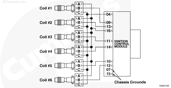
Ignition Timing Signal Circuit |
 |
;)
;)
Circuit Description
The ignition control module (ICM) is a distributorless ignition module that provides a signal to the coils and delivers high voltage to the spark plugs. The electronic control module (ECM) controls the ICM by providing ignition timing information. The ICM is capable of misfire and spark voltage detection.
Component Location
The ICM is located next to the ECM on the side of the engine.
Shop Talk
This fault code is designed to inform the technician a potential problem with the ignition harness or ICM. The most probable cause for this fault code to occur will be from an ignition harness short or open.
Troubleshooting Steps
| STEPS | SPECIFICATIONS | |
|---|---|---|
| STEP 1. | Check the fault codes. | |
| STEP 1A. Check for an inactive fault code. | Fault Code 1652 inactive? | |
| STEP 2. | Check the ICM and ignition harness. | |
| STEP 2A. Inspect the ICM ignition harness connector pins. | Dirty or damaged pins? | |
| STEP 2B. Check for an open circuit in the ignition harness. | Less than 10 ohms? | |
| STEP 2B-1. Check for an open circuit in the ignition harness. | ||
| STEP 2C. Check for a pin short circuit to ground. | Greater than 100k ohms? | |
| STEP 2D. Check for a pin to pin short circuit in the ignition harness. | Greater than 100k ohms? | |
| STEP 2E. Check for an inactive fault code. | Fault Code 1652 inactive? | |
| STEP 3. | Clear the fault code. | |
| STEP 3A. Disable the fault code. | Fault Code 1652 inactive? | |
| STEP 3B. Clear the inactive fault codes. | All fault codes cleared? | |
Guided Step 1 – Check the fault codes.
| Guided Step 1A – Check for an inactive fault code. | |
|---|---|
Conditions
Action
|
|
|
Fault Code 1652 inactive? |
|
| YES | NO |
| No Repair | No Repair |
|
Procedure 019-362
|
|
Guided Step 2 – Check the ICM ignition harness.
| Guided Step 2A – Inspect ICM and ignition harness connector pins. | |
|---|---|
Conditions
Action
For general inspection techniques, refer to Component Connector and Pin Inspection, Procedure 019-361. |
|
|
Dirty or damaged pins? |
|
| YES | NO |
|
A defective connection has been detected in the ICM or ignition harness connectors. Repair the damaged pins. Repair or replace the harness, whichever has the damaged pins.
|
No Repair |
| Guided Step 2B – Check for an open circuit in the ignition harness. | |
|---|---|
Conditions
Action
Refer to the circuit diagram or wiring diagram for connector pin identification. For general resistance measurement techniques, refer to Resistance Measurements Using a Multimeter and Wiring Diagram, Procedure 019-360 |
|
|
Less than 10 ohms? |
|
| YES | NO |
| No Repair |
An open signal circuit has been detected in the ignition harness. Repair or replace the ignition harness.
|
| Guided Step 2B-1 – Check for an open circuit in the ignition harness. | |
|---|---|
Conditions
Action
Note: All spark return signal wires in the ignition harness are tied together. This way there will be continuity through each spark signal pin of each coil to the main spark return signal wire at the ignition harness connector C2. If one of the spark signal circuits is found to be open, then the ICM will think that the engine is misfiring when it is not. Refer to the circuit diagram or wiring diagram for connector pin identification. For general resistance measurement techniques, refer to Resistance Measurements Using a Multimeter and Wiring Diagram, Procedure 019-360 |
|
|
Less than 10 ohms? |
|
| YES | NO |
| No Repair |
A open signal circuit has been detected in the ignition harness. Repair or replace the ignition harness.
|
| Guided Step 2C – Check for a pin short to ground. | |
|---|---|
Conditions
Action
Refer to the circuit diagram or wiring diagram for connector pin identification. For general resistance measurement techniques, refer to Resistance Measurements Using a Multimeter and Wiring Diagram, Procedure 019-360 |
|
|
Greater than 100k ohms? |
|
| YES | NO |
| No Repair |
A pin to ground short circuit has been detected in the ignition harness. Repair or replace the ignition harness.
|
| Guided Step 2D – Check for a pin to pin short circuit in the ignition harness. | |
|---|---|
Conditions
Action
Refer to the circuit diagram or wiring diagram for connector pin identification. For general resistance measurement techniques, refer to Resistance Measurements Using a Multimeter and Wiring Diagram, Procedure 019-360 |
|
|
Greater than 100k ohms? |
|
| YES | NO |
| No Repair |
A pin to pin short circuit has been detected in the ignition harness. Repair or replace the ignition harness.
|
| Guided Step 2E – Check for an inactive fault code. | |
|---|---|
Conditions
Action
|
|
|
Fault Code 1652 inactive? |
|
| YES | NO |
|
Note: The removal and installation of the connectors corrected the failure. |
|
Guided Step 3 – Clear the fault codes.
| Guided Step 3A – Disable the fault code. | |
|---|---|
Conditions
Action
|
|
|
Fault Code 1652 inactive? |
|
| YES | NO |
| No Repair | No Repair |
| Guided Step 3B – Clear the inactive fault codes. | |
|---|---|
Conditions
Action
|
|
|
All fault codes cleared? |
|
| YES | NO |
| No Repair | No Repair |
|
Repair complete
|
Appropriate troubleshooting steps
|