|
Accelerator Pedal or Lever Idle Validation Circuit – Out of Calibration
|

Overview
| CODE | REASON | EFFECT |
| Fault Code: 432 PID: S230 SPN: 558 FMI: 13/13 LAMP: Red SRT: |
Accelerator Pedal or Lever Idle Validation Circuit – Out of Calibration. Voltage at idle validation on-idle and off-idle circuit does not match accelerator pedal position. |
Engine will only idle. |
|
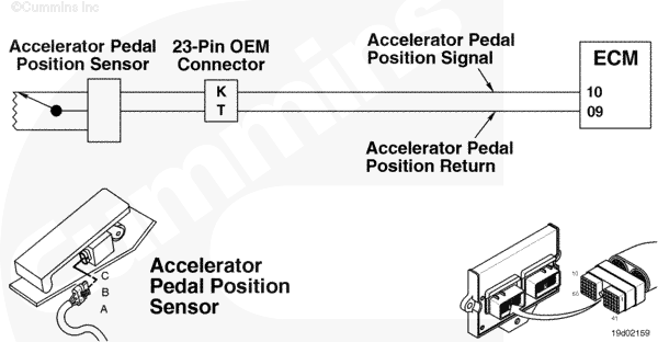
Accelerator Pedal or Lever Idle Validation Circuit |
 |
Circuit Description
The accelerator pedal or lever position sensor is attached to the accelerator pedal or lever. The accelerator pedal or lever position sensor sends a signal to the electronic control module (ECM) when the accelerator pedal or lever is depressed or released. The accelerator pedal or lever position circuit contains three wires: accelerator pedal or lever position supply, accelerator pedal or lever position return, accelerator pedal or lever position signal. The switch return circuit for the on-idle and off-idle validation circuit is a shared return with other OEM switches.
Component Location
The accelerator pedal or lever position sensor is located on the accelerator pedal or lever.
Shop Talk
This fault is logged when both the on- idle and off-idle validation switches disagree with the accelerator pedal or lever position signal. Turning the keyswitch ON while partially depressing the accelerator pedal or lever can cause this fault code to go active. This fault will stay active until the pedal or lever is cycled through its full travel.
Cautions and Warnings
 WARNING WARNING On automotive applications, set the service brake using the trailer brake hand valve. Make sure there is enough air pressure to activate the brake pressure switch. Securely chock the wheels. Truck movement during troubleshooting can cause severe equipment damage, personal injury or death.
|
 CAUTION CAUTION To reduce the possibility of damaging a new ECM, all other active fault codes must be investigated prior to replacing the ECM. |
|
CAUTION To reduce the possibility of pin and harness damage, use the following test leads when taking a measurement: |
Troubleshooting Steps
| STEPS | SPECIFICATIONS | |
|---|---|---|
| STEP 1. | Check the fault codes. | |
| STEP 1A. Check for an active fault code. | Fault Code 432 active? | |
| STEP 2. | Check the OEM harness. | |
| STEP 2A. Inspect the engine harness and ECM connector pins. | Dirty or damaged pins? | |
| STEP 2B. Check the accelerator pedal or lever position sensor resistance. | 1500 to 3000 ohms (released), 250 to 1500 ohms (depressed)? | |
| STEP 3B-1. Check the resistance of the accelerator pedal or lever position sensor. | ||
| STEP 2C. Check for a pin to pin short. | Greater than 100k ohms? | |
| STEP 3. | Check the fault codes. | |
| STEP 3A. Perform the fault code disable procedure | Fault Code 432 active? | |
| STEP 4. | Clear the fault codes. | |
| STEP 4A. Disable the fault codes. | Fault Code 423 inactive? | |
| STEP 4B. Clear the inactive fault codes. | All fault codes cleared? | |
Guided Step 1 – Check the fault codes.
| Guided Step 1A – Check for an active fault code. | |
|---|---|
Conditions
Action
|
|
|
Fault Code 432 active? |
|
| YES | NO |
| No Repair | No Repair |
Guided Step 2 – Check the OEM harness.
| Guided Step 2A – Inspect the engine harness and ECM connector pins. | |
|---|---|
Conditions
Action
For general inspection techniques, refer to Component Connector and Pin Inspection, Procedure 019-361. |
|
|
Dirty or damaged pins? |
|
| YES | NO |
|
A defective connection has been detected in the ECM connector or engine harness connector. Repair the damaged pins. Repair or replace the engine harness, whichever has the damaged pins. |
No Repair |
| Guided Step 2B – Check the accelerator pedal or lever position sensor resistance. | |
|---|---|
Conditions
Action
Refer to the circuit diagram or wiring diagram for connector pin identification. For general resistance measurement techniques, refer to Resistance Measurements Using a Multimeter and Wiring Diagram, Procedure 019-360. |
|
|
1500 to 3000 ohms released, 250 to 1500 ohms depressed? Released value must be at least 1000 ohms greater than depressed value. |
|
| YES | NO |
| No Repair | No Repair |
| Guided Step 2B-1 – Check the resistance of the accelerator pedal or lever position sensor. | |
|---|---|
Conditions
Action
Refer to the circuit diagram or wiring diagram for connector pin identification. For general resistance measurement techniques, refer to Resistance Measurements Using a Multimeter and Wiring Diagram, Procedure 019-360. |
|
|
1500 to 3000 ohms released, 250 to 1500 ohms depressed? Released value must be at least 1000 ohms greater than depressed value. |
|
| YES | NO |
|
Repair the damaged pins. Repair or replace the OEM or engine harness, whichever has the damaged pins.
|
Replace the accelerator pedal. Refer to the OEM service manual. |
| Guided Step 2C – Check for a pin to pin short. | ||
|---|---|---|
Conditions
Action
Refer to the circuit diagram or wiring diagram for connector pin identification. For general resistance measurement techniques, refer to Resistance Measurements Using a Multimeter and Wiring Diagram, Procedure 019-360. |
|
|
|
Greater than 100k ohms? |
||
| YES | NO | |
| No Repair |
Repair the damaged pins. Repair or replace the OEM or engine harness, whichever has the damaged pins.
|
|
;)
;)
;)
;)
Guided Step 3 – Check the fault codes.
| Guided Step 3A – Perform the fault code disable procedure. | |
|---|---|
Conditions
Action
|
|
|
Fault Code 432 active? |
|
| YES | NO |
| No Repair |
Replace the accelerator pedal or lever assembly. Refer to the equipment manufacturer’s troubleshooting and repair manual. |
Guided Step 4 – Clear the fault code.
| Guided Step 4A – Disable the fault code. | |
|---|---|
Conditions
Action
|
|
|
Fault Code 432 inactive? |
|
| YES | NO |
| No Repair | No Repair |
| Guided Step 4B – Clear the inactive fault codes. | |
|---|---|
Conditions
Action
|
|
|
All fault codes cleared? |
|
| YES | NO |
| No Repair | No Repair |
|
Repair complete
|
Appropriate troubleshooting steps
|