|
Wastegate Control Valve Stuck Open
|

Overview
Wastegate Control Valve Stuck Open
| CODE | REASON | EFFECT |
| Fault Code: 545 PID: S32 SPN: 1188 FMI: 7 LAMP: Yellow SRT: |
Turbocharger control valve stuck open. |
Possible turbocharger overspeed. |
|
Turbocharger Control Valve Circuit |
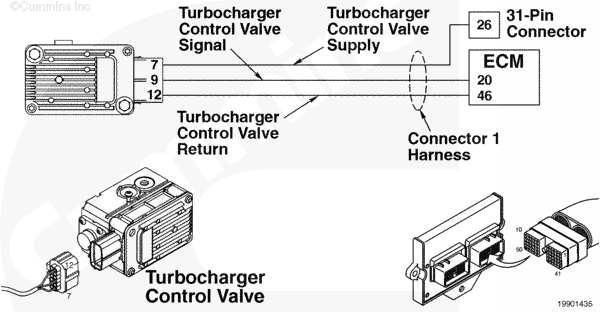 |
Circuit Description
The electronic control valve (ECM) controls the variable geometry actuator position with the turbocharger control valve. The turbocharger control valve controls the air pressure to the variable geometry actuator when commanded by the ECM. ECM commands are sent to the control valve through the turbocharger control valve signal of the ECM engine harness.
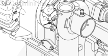
Component Location
The turbocharger control valve is located on the fuel housing.
Shop Talk
Turbocharger control valve command can be monitored with INSITE™ electronic service tool. This parameter represents the ECM command to the turbocharger control valve which in turn controls the variable geometry actuator position.
Possible causes of this fault code include:
- Signal short circuit to ground
- Short circuit to ground in the turbocharger control valve.
Troubleshooting Steps
| STEPS | SPECIFICATIONS | |
|---|---|---|
| STEP 1. | Read the fault codes. | |
| STEP 1A. Check for overboost Fault Code 124. | Fault Code 124 active? | |
| STEP 2. | Check the turbocharger. | |
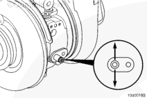
| STEP 2A. Check variable geometry actuator rod for correct travel. | Does the turbocharger actuator rod extend between 10.8 mm and 11.8 mm [0.42 and 0.46 in]? | |
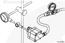
| STEP 2A-1. Check for air leaks and inspect air lines. | ||
| STEP 2A-2. Check for air pressure at the turbocharger control valve outlet. | ||
| STEP 2A-3. Check for air pressure at turbocharger control valve outlet. | ||
| STEP 2A-4. Check for vehicle air tank pressure at turbocharger control valve inlet. | ||
| STEP 2A-5. Check for correct turbocharger actuator travel. | ||
| STEP 2B. Check for broken shaft inside the turbocharger. | Does the sliding nozzle move correctly? | |
| STEP 3. | Clear the fault codes. | |
| STEP 3A. Disable the fault code. | Fault Code 545 inactive? | |
| STEP 3B. Clear the inactive fault codes. | All fault codes cleared? | |
Guided Step 1 – Read the fault codes.
| Guided Step 1A – Check for overboost Fault Code 124. | |
|---|---|
Conditions
ActionUse INSITE™ electronic service tool to read the fault codes. |
|
|
Fault Code 124 active? |
|
| YES | NO |
| No Repair | No Repair |
|
Fault Code 124
|
|
Guided Step 2 – Check the turbocharger.
| Guided Step 2A – Check variable geometry actuator rod for correct travel. | ||
|---|---|---|
Conditions
Action
Note: The variable geometry actuator must move quickly and crisply. If the actuator rod movement is slow. there can possibly be a problem with the variable geometry turbocharger. |
|
|
|
Does the turbocharger actuator rod extend between 10.8 mm and 11.8 mm [0.42 and 0.46 in]? |
||
| YES | NO | |
| No Repair | No Repair | |
| Guided Step 2A-1 – Check for air leaks and inspect air lines. | |
|---|---|
Conditions
ActionSelect the “Extended Actuator” position. Listen for air leaks in the following components:
Note: A small amount of air will be heard escaping from the Turbocharger Control Valve. This is a normal condition. Do not replace the Turbocharger Control Valve for this condition. |
|
|
Air leaks found in the system or damaged air lines? |
|
| YES | NO |
|
Repair air leaks or replace damaged air lines. |
No Repair |
| Guided Step 2A-2 – Check for air pressure at the turbocharger control valve outlet. | |
|---|---|
Conditions
Action
|
|
|
Is vehicle tank air pressure present at the Turbocharger Control Valve outlet? |
|
| YES | NO |
| No Repair | No Repair |
| Guided Step 2A-3 – Check for air pressure at Turbocharger Control Valve outlet. | |
|---|---|
Conditions
Action
|
|
|
Can air be heard escaping from the Turbocharger Control Valve outlet? |
|
| YES | NO |
|
The Turbocharger Control Valve is stuck open. It must not be allowing air to escape when in the “Retract” position. Replace the Turbocharger Control Valve. Refer to Procedure 019-388. |
No Repair |
| Guided Step 2A-4 – Check for vehicle air tank pressure at Turbocharger Control Valve inlet. | |
|---|---|
Conditions
Action
|
|
|
Vehicle air tank pressure available at the Turbocharger Control Valve inlet? |
|
| YES | NO |
| No Repair |
No air pressure available at the Turbocharger Control Valve inlet. Troubleshoot OEM air plumbing and determine why air pressure is not present. |
| Guided Step 2A-5 – Check for correct turbocharger actuator travel. | ||
|---|---|---|
Conditions
Action
|
|
|
|
Does the variable geometry actuator rod travel at least 12 mm [0.472 in]? |
||
| YES | NO | |
|
The variable geometry actuator has correct air pressure and correct travel. The variable geometry mechanism in the turbocharger is seized. Replace the turbocharger assembly. Refer to Procedure 010-033 in the Troubleshooting and Repair Manual, C Gas, C Gas Plus, and L Gas Plus Engines, Bulletin 3666206. |
Variable geometry actuator has correct air pressure but variable geometry actuator rod is not extending. Replace the turbocharger actuator. Refer to Procedure 010-113 in the Troubleshooting and Repair Manual, C Gas, C Gas Plus, and L Gas Plus Engines, Bulletin 3666206. |
|
| Guided Step 2B – Check for broken shaft inside the turbocharger. | ||
|---|---|---|
Conditions
Action
Note: The actuator lever must move evenly and crisp as it is moved. |
|
|
|
Does the sliding nozzle move correctly? |
||
| YES | NO | |
| No Repair |
The variable geometry turbocharger has a mechanical failure inside the turbocharger. The actuator moves properly, but the linkage attaching the actuator to the nozzle is broken. Replace the turbocharger assembly. Refer to Procedure 010-033 in the Troubleshooting and Repair Manual, C Gas, C Gas Plus, and L Gas Plus Engines, Bulletin 3666206. |
|
;)
;)
;)
;)
;)
;)
;)
;)
Guided Step 3 – Clear the fault codes.
| Guided Step 3A – Disable the fault code. | |
|---|---|
Conditions
Action
|
|
|
Fault Code 545 inactive? |
|
| YES | NO |
| No Repair |
Troubleshooting procedures need to be repeated from the beginning. |
| Guided Step 3B – Clear the inactive fault codes. | |
|---|---|
Conditions
Action
|
|
|
All fault codes cleared? |
|
| YES | NO |
| No Repair |
Troubleshoot any remaining active fault codes. |
|
Repair complete
|
Appropriate troubleshooting charts
|