Batteries can emit explosive gases. To reduce the possibility of personal injury, always ventilate the compartment before servicing the batteries. To reduce the possibility of arcing, remove the negative (-) battery cable first and attach the negative (-) battery cable last.
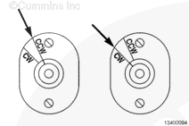
1) Bar the engine until the timing indicator on the front of the engine is at the prescribed ignition timing value. Check the alignment of the indicator on the rear of the ignition generator. The marks should be near alignment on the clockwise (CW) mark. If the marks are approximately 180 degrees out of alignment, rotate the engine an additional 360 degrees and check the rear alignment of the ignition again.
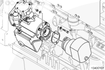
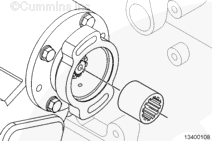
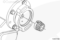
2) Disconnect the wiring harness. Remove the two mounting capscrews on the ignition generator. Remove the generator and discard the gasket.
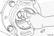
Remove the splined coupling and inspect it for wear. Discard if wear is found.
Manually check if there is any hub-to-shaft play and check if the set screw is tight. If no play is found, and the set screw is tight, proceed to installation of the spline coupling and ignition generator.
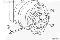
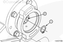
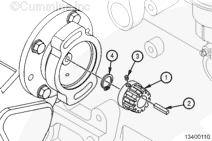
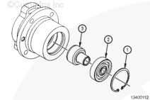
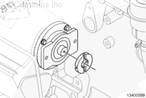
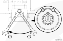
Loosen the set capscrew (3) in the rear rim of the splined coupling hub (1) with a 7/16 inch 12 point box end wrench. Inspect for wear on the inner surface of the spline hub (1) and for any wear on the key (2). If any sign of wear is found on either piece, discard both.
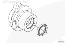
NOTE: If an oil leak is not present, skip to Assembly process.
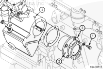
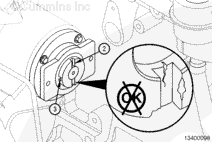
Remove the four mounting capscrews (1) on the ignition timer support. Install two bolts into the ignition timer support (3) removal points (2). This will allow for the ignition timer support and the square key (4) to be removed from the governor housing. Discard the gasket and replace the square key if necessary.
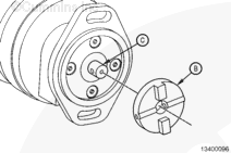
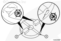
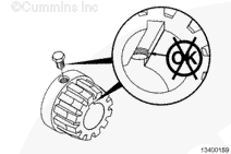
Inspect the ignition coupling for cracks, deformities, or any other damage. Pay special attention to the coupling teeth (D), as well as the spring pin bore area (E).
Replace all worn or damaged couplings and spring pins.
Install the ignition timer support (3) with a new gasket onto the accessory drive shaft. Install the square key (4) into the keyway. Tighten the mounting capscrew (1).
Drive the spring (A) through the coupling (B) and the shaft (C) until it is flush with the coupling outside diameter.
Fill the governor housing with oil to the recommended level on the dipstick. Refer to Procedure 015-006 in Section 6 of the GTA28 Operation and Maintenance Manual, Bulletin 4021558.
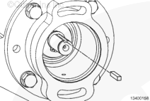
Insert the key into the keyway on the accessory drive shaft. Slide the key back onto the shaft until it is firmly seated in the keyway against the snap ring.
Tighten the capscrew with a 7/16 inch 12 point box end wrench.
Place the wrench on the capscrew with the handle as close to the housing as possible. The illustration shows the capscrew at the 12 o’clock position. Rotate the wrench from position 1 to position 2 (at the opposite end of the housing), as illustrated.
NOTE: Overtightening the set screw may cause the hub to crack.
Install the new gasket onto the ignition generator.
Use the two mounting capscrews and install the ignition generator on the engine, keeping the two red lines on the back of the unit aligned as closely as possible.
If the two lines do not meet, loosen the back cover by removing the four fastening screws and carefully tilting the top of the cover away from the unit, keeping the internal plug connected. Rotate the distributor shaft until the marks are aligned. Install the cover and securely tighten the four fastening screws.
Tighten the mounting capscrews and connect the wiring harness.
Batteries can emit explosive gases. To reduce the possibility of personal injury, always ventilate the compartment before servicing the batteries. To reduce the possibility of arcing, remove the negative (-) battery cable first and attach the negative (-) battery cable last.
Hello, I'm Jack, a diesel engine fan and a blogger. I write about how to fix and improve diesel engines, from cars to trucks to generators. I also review the newest models and innovations in the diesel market. If you are interested in learning more about diesel engines, check out my blog and leave your feedback.
View all posts by Jack
 WARNING


;)
;)
;)
;)
;)
;)
;)
;)
;)
;)
;)
;)
;)
;)
;)
;)
;)
;)
;)
;)
;)
;)
;)
;)
;)
;)
;)
;)
;)
;)
;)
;)
;)
;)
;)
;)
;)
;)