The fuel pump, high-pressure fuel lines, and fuel rail contain very high-pressure fuel. Do not loosen any fittings while the engine is running. Wait at least 10 minutes after shutting down the engine before loosening any fittings in the high-pressure fuel system to allow pressure to decrease to a lower level.
WARNING
Depending on the circumstances, diesel fuel is flammable. When inspecting or performing service or repairs on the fuel system, to reduce the possibility of fire and resulting severe personal injury, death or property damage, never smoke or allow sparks or flames (such as pilot lights, electrical switches, or welding equipment) in the work area.
CAUTION
Use caution when disconnecting or removing fuel lines, replacing filters and priming the fuel system that fuel is not spilled or drained into the bilge area. Do not drop or throw filter elements into the bilge area. The fuel and fuel filters must be discarded in accordance with local environmental regulations.
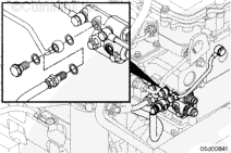
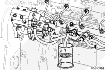
This fuel pump head leakage test uses a flow adapter fitting. The purpose of the flow adapter fitting is to route the drain flow of the fuel pump only into a collection device so that leakage may be measured.
Perform the Fuel Pump Head Leakage Test described below.
If the drain manifold is not easily accessed, a M14 banjo may be attached at the pump head drain port with a fuel hose that is routed to the collection container.
In this setup, a bolt, nut, and washers are needed to prevent fuel from flowing backwards and leaking from the unused drain line.
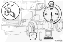
The high-pressure leakage test in INSITE™ electronic service tool will cause the engine to operate at elevated pressures while the engine idles. The engine noise will change when this test is being performed due to the higher fuel injection pressures. Safety glasses should be worn while working near the running engine. Fuel lines should not be adjusted while performing this test.
Close the engine cover(s) while performing these tests.
Fuel Pump Head Leakage Test (Engine Will Not Start)
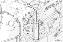
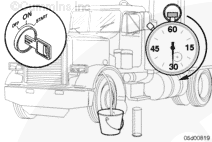
Turn the keyswitch ON and allow the lift pump to complete its cycle. After the cycle is completed, begin cranking the engine until fuel exits the drain line.
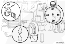
When fuel begins to exit the drain line, route the drain flow to a graduated cylinder and continue cranking for 30 seconds.
This specification is valid for engines operating on diesel fuels. Low fuel viscosity will increase the leakage rate; for example, kerosene or aviation fuels will result in excessive leakage. Verify the fuel type before replacing a fuel pump head for excessive leakage.
Maximum Volume of Fuel During Fuel Pump Head Leakage Test
Batteries can emit explosive gases. To reduce the possibility of personal injury, always ventilate the compartment before servicing the batteries. To reduce the possibility of arcing, remove the negative (-) battery cable first and attach the negative (-) battery cable last.
WARNING
Depending on the circumstances, diesel fuel is flammable. When inspecting or performing service or repairs on the fuel system, to reduce the possibility of fire and resulting severe personal injury, death or property damage, never smoke or allow sparks or flames (such as pilot lights, electrical switches, or welding equipment) in the work area.
WARNING
Do not bleed the fuel system of a hot engine; this can result in fuel spilling onto a hot exhaust manifold, which can cause a fire.
Disconnect the batteries. Refer to the OEM service manual.
Close the fuel supply and drain valves. Refer to the OEM service manual.
Batteries can emit explosive gases. To reduce the possibility of personal injury, always ventilate the compartment before servicing the batteries. To reduce the possibility of arcing, remove the negative (-) battery cable first and attach the negative (-) battery cable last.
WARNING
Depending on the circumstances, diesel fuel is flammable. When inspecting or performing service or repairs on the fuel system, to reduce the possibility of fire and resulting severe personal injury, death or property damage, never smoke or allow sparks or flames (such as pilot lights, electrical switches, or welding equipment) in the work area.
WARNING
Do not bleed the fuel system of a hot engine; this can result in fuel spilling onto a hot exhaust manifold, which can cause a fire.
CAUTION
Use caution when disconnecting or removing fuel lines, replacing filters and priming the fuel system that fuel is not spilled or drained into the bilge area. Do not drop or throw filter elements into the bilge area. The fuel and fuel filters must be discarded in accordance with local environmental regulations.
Disconnect the batteries. Refer to the OEM service manual.
Close the fuel supply and drain valves. Refer to the OEM service manual.
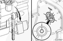
Remove the last two capscrews. Alternately loosen the capscrews to avoid binding. Loosen each capscrew about one turn at a time.
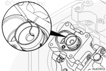
Carefully lift the fuel pump head from the camshaft housing, being careful to keep the tappet springs attached to the pump head. Place the head on a clean surface.
Wear appropriate eye and face protection when using compressed air. Flying debris and dirt can cause personal injury.
Special care must be taken to be sure these parts are kept extremely clean if removed. Cover the camshaft housing with a clean shop towel while the head is removed.
Do not use cleaning agents, other than contact cleaner, on pump components.
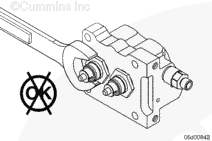
NOTE: Do not perform the following test without the springs and spring retainers installed.
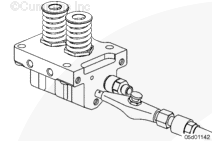
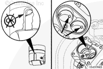
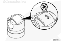
With the springs and spring retainers installed, blow compressed air (at least 138 kPa [20 psi]) into the fuel inlet port of the fuel pump head.
The plungers should extend to the tappet spring retainers. If the pumping plungers are stuck and do not extend to the tappet spring retainers, replace the fuel pump head.
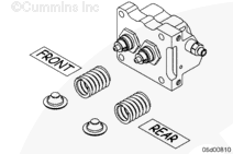
Remove the springs and spring retainers from the barrel retainers.
Make certain to keep track of which spring came from the front and rear. It is recommended that these parts be installed in the same location, even if a new high-pressure pump head is installed.
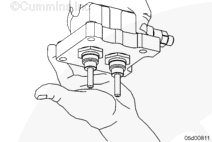
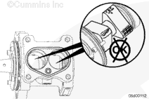
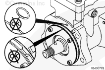
Press on the pumping plungers to make sure they are not binding in the barrel.
If the pump head check valves are working correctly, the pumping plungers will spring back to their original position. If the plungers do not spring back, replace the fuel pump head.
Each plunger must be installed in the same orientation and in the same barrel, or engine damage can result. Marking the bottoms of the plungers with a felt tip marker will help to make sure that correct orientation is maintained.
If the plungers are removed, inspect the plungers. Slight discoloration can be evident. Deep scoring must not be present. If scoring or scratches exist that can be felt, the fuel pump head must be replaced.
NOTE: Some fuel pump heads are built with non-symmetric pumping plungers. The crowned end of the pumping plunger must be installed into the barrel. If the plunger is installed in the wrong orientation, fuel pump head damage will result.
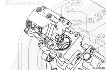
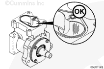
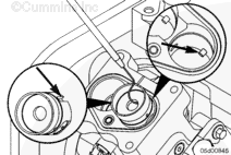
Inspect the tappet guide pins and tappet guide pin grooves for excessive wear. If more than 25-percent guide pin or groove wear is observed, the fuel pump must be replaced.
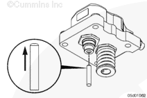
Normal operation creates vertical grooves in the cylinder bores of the fuel pump camshaft housing. These grooves are not an indication of a malfunction.
Camshaft housings with grooves are acceptable for reuse.
With the camshaft housing tappets removed, inspect the camshaft for wear. If excessive pitting on the nose of the camshaft is observed, the fuel pump must be replaced.
If damage to the camshaft, tappets, or camshaft housing is observed, it is possible the fuel pump is not receiving adequate lubricating oil. When replacing the fuel pump, inspect the gear housing to make sure no blockages exist in the oil supply to the fuel pump.
Install new fuel pump head o-rings onto the camshaft housing.
If installing a new or rebuilt pump head, install the new tappet springs and retainers provided with the pump head.
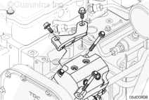
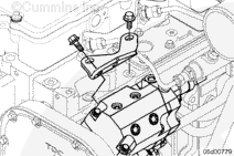
Place the high-pressure pump head onto the high-pressure pump camshaft housing.
Draw the high-pressure pump head down by alternately tightening the four high-pressure pump head capscrews until the head just contacts the camshaft housing.
Tighten the four high-pressure pump head capscrews to the final torque.
Batteries can emit explosive gases. To reduce the possibility of personal injury, always ventilate the compartment before servicing the batteries. To reduce the possibility of arcing, remove the negative (-) battery cable first and attach the negative (-) battery cable last.
Batteries can emit explosive gases. To reduce the possibility of personal injury, always ventilate the compartment before servicing the batteries. To reduce the possibility of arcing, remove the negative (-) battery cable first and attach the negative (-) battery cable last.
Hello, I'm Jack, a diesel engine fan and a blogger. I write about how to fix and improve diesel engines, from cars to trucks to generators. I also review the newest models and innovations in the diesel market. If you are interested in learning more about diesel engines, check out my blog and leave your feedback.
View all posts by Jack
 WARNING
  CAUTION
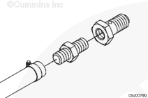


;)
;)
;)
;)
;)
;)
;)
;)
;)
;)
;)
;)
;)
;)
;)
;)
;)
;)
;)
;)
;)
;)
;)
;)
;)
;)
;)
;)
;)
;)
;)
;)
;)
;)
;)
;)
;)
;)
;)
;)
;)
;)
;)
;)
;)
;)
;)
;)
;)
;)