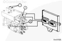
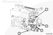
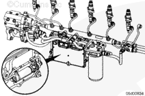
The Cummins accumulator pump system (CAPS) fuel system is a distributor-type injection system. An accumulator is used to store pressurized fuel for the injection event. There are four components that provide or receive input to the electronic control module (ECM). There are two pumping control valves (1) that are controlled by the ECM. These valves control the pressure in the accumulator. The accumulator fuel pressure/temperature (2) sensor is located on the accumulator and provides the ECM with pressure and temperature information. The injection control valve (3) is also controlled by the ECM and regulates fuel injected into the cylinder.
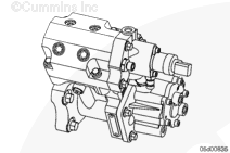
The CAPS injection pump can be divided into six distinct units/modules. They are the gear pump, cam housing, accumulator, rate shape tube, injection control valve (ICV), and distributor. Fuel flows through the modules in the following order:
A lift pump is used for priming the pump at start-up. The lift pump runs for approximately 30 seconds after key-on. Once the engine is started, the gear pump is able to maintain prime without any assistance from the lift pump.
The gear pump supplies fuel to the pumping plungers through internal drillings in the cam housing. The gear pump also supplies fuel to the distributor for lubrication. The fuel pressure is regulated to approximately 160 psi at rated engine rpm. The gear pump has an internal filter to catch any debris generated downstream of the main, external fuel filter. The pump camshaft is driven off the engine camshaft; therefore, pump rpm is one-half engine rpm. The gear pump is driven by the pump camshaft through an internal coupling. The gear pump shaft then turns the distributor rotor through a second internal coupling.
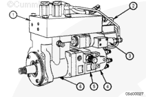
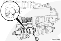
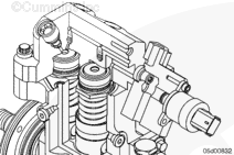
Each of the two pumping plungers is driven by a three lobed camshaft (3). The camshaft is located in the cam housing module by tapered roller bearings. The bearings that support the camshaft, as well as the tappets (2), rollers (1), and camshaft itself are lubricated with engine oil. These are the only components in the pump lubricated with engine oil.
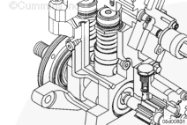
A pumping control valve (2) is located above each pumping plunger (1). The supply fuel from the gear pump flows around the plunger of this normally open valve into the chamber above the plunger. The volume above each pumping plunger is filled, by the gear pump, as the plungers travel downward. As the plunger starts to move upward, the fuel is pushed backward into the gear pump. When the pumping control valve closes, the fuel is pushed into the accumulator and then held by check valves. The time when the pumping control valve is energized (closed) is based on engine speed, accumulator pressure, and throttle position. A 0- to 24,000-psi pressure sensor is located in the accumulator. The pressure sensor provides direct feedback to the ECM, so the desired accumulator pressure is maintained. This pressure sensor also has temperature sensing capabilities built into it. Fuel moves from the accumulator to the distributor and through the rate shape tube (3).
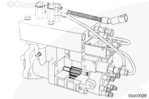
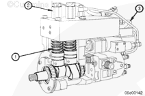
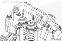
Fuel is delivered to the injection control valve (1) by the rate shape tube and through a drilling in the distributor (2). The ICV controls both fueling and timing. The injection control valve contains an inner pin and outer valve. The outer valve is moved by magnetic force generated inside the ICV by a current from the ECM. The inner pin is moved by spring force and fuel pressure. When the two pins are in the closed position, no fuel flows through the control valve. The position of these internal parts controls fuel flow to the distributor rotor (3) and to the drain (4). The injection control valve opens and closes once for each injection event.
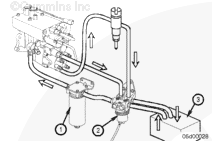
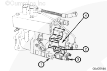
The distributor (1) directs the fuel to the correct injector using the rotor. The drain fuel from the ICV is routed through the ICV pressure regulator (4) and is returned to the tank.
The position of the rotor directs the fuel to one of six drillings in the distributor housing. These drillings communicate the fuel to six fuel pump delivery valves (3). There is one injector line per delivery valve. The injection line carries the fuel to the injector.
The Cummins Common Rail Fuel System is a high-pressure common rail injection system. A fuel rail is used to store pressurized fuel for fuel injection. There are four components that provide or receive input to the electronic control module (ECM). The ECM powers the electric fuel lift pump (located behind the ECM) for approximately 30 seconds at key-on to prime the fuel system. The normally open fuel pump actuator receives a pulse width modulated (PWM) signal from the ECM to open or close in response to the signal from the fuel rail pressure sensor. The injectors have individual solenoids. The ECM powers each injector individually to provide fueling to each cylinder.
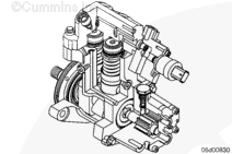
The high-pressure fuel pump can be divided into four distinct assemblies. They are the fuel gear pump, fuel pump actuator housing, cam housing, and high-pressure fuel pump head. Fuel flows through the gear pump to a 2-micron pressure-side filter. After the pressure-side filter, fuel enters the fuel pump actuator housing. The fuel pump actuator housing includes an air-bleed fitting and the fuel pump actuator. Some fuel continuously returns to drain through the air-bleed orifice fitting. Fuel that is metered through the fuel pump actuator enters the high-pressure fuel pump head where it is pumped to fuel rail pressure and exits at the high-pressure outlet fitting.
A lift pump is used for priming the gear pump at start-up. The lift pump runs for approximately 30 seconds after key-on. Once the engine is started, the gear pump is able to maintain prime without any assistance from the lift pump.
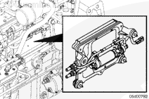
The ECM and ECM cooling plate must be removed to access the lift pump and lift pump fuel lines. This is accomplished by disconnecting the engine harnesses and the quick disconnect style fuel lines first. Removal of the ECM cooling plate capscrews allows the ECM, cooling plate, lift pump and lift pump plumbing to be removed as one assembly.
Each of the two pumping plungers is driven by a three lobed camshaft. The camshaft is located in the cam housing module by tapered roller bearings. The bearings that support the camshaft, as well as the tappets, rollers and camshaft itself are lubricated with engine oil. These are the only components in the pump lubricated with engine oil.
Engine oil to the high-pressure pump is supplied through a drilling in the engine gear housing. The oil passes from the engine gear housing to the high-pressure pump cam housing. A small o-ring in a recess on the back of the engine gear housing seals this passage.
Pressurized fuel from the gear pump is supplied to the fuel pump actuator. The fuel pump actuator is opened or closed by the ECM to maintain the appropriate fuel rail pressure.
An air-bleed orifice fitting in the fuel pump actuator housing aids in purging air from the fuel supply. Because of the air-bleed orifice fitting, some fuel that is supplied by the gear pump will return to drain at all times.
Fuel that is metered past the fuel pump actuator enters the high-pressure fuel pump inlet drilling, past the inlet check valve and fills the pumping chamber by pressing the pumping plunger downward. When the camshaft pushes the pumping plunger upward, fuel reaches rail pressure and causes the outlet check valve to lift. Fuel then enters the outlet drilling of the fuel pump and exits the high pressure fuel line to the fuel rail.
Hello, I'm Jack, a diesel engine fan and a blogger. I write about how to fix and improve diesel engines, from cars to trucks to generators. I also review the newest models and innovations in the diesel market. If you are interested in learning more about diesel engines, check out my blog and leave your feedback.
View all posts by Jack
;)
;)
;)
;)
;)
;)
;)
;)
;)
;)
;)
;)
;)
;)
;)
;)
;)
;)
;)
;)
;)
;)
;)
;)
;)
;)
;)
;)
;)
;)