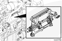
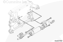
The ECM cooling plate assembly provides a vibration isolated mounting location for the ECM. The cooling plate also provides ECM cooling and incorporates the fuel lift pump. A check valve at the outlet port in the ECM cooling plate makes sure that the fuel system is primed while the fuel lift pump is running.
Check the ECM cooling plate for damaged vibration isolators, loose capscrews, or fuel leaks.
Batteries can emit explosive gases. To reduce the possibility of personal injury, always ventilate the compartment before servicing the batteries. To reduce the possibility of arcing, remove the negative (-) battery cable first and attach the negative (-) battery cable last.
WARNING
Fuel is flammable. Keep all cigarettes, flames, pilot lights, arcing equipment, and switches out of the work area and areas sharing ventilation to reduce the possibility of severe personal injury or death when working on the fuel system.
WARNING
Wear appropriate eye and face protection when using compressed air. Flying debris and dirt can cause personal injury.
WARNING
When using a steam cleaner, wear safety glasses or a face shield, as well as protective clothing. Hot steam can cause serious personal injury.
CAUTION
Use caution when disconnecting or removing fuel lines, replacing filters and priming the fuel system that fuel is not spilled or drained into the bilge area. Do not drop or throw filter elements into the bilge area. The fuel and fuel filters must be discarded in accordance with local environmental regulations.
CAUTION
Clean all fittings before disassembly. Dirt or contaminants can damage the fuel system.
Before servicing any fuel system components, (such as fuel lines, fuel pump, injectors, etc.) which would expose the fuel system or internal engine component to potential contaminants prior to disassembly, clean the fittings, mounting hardware, and the area around the component to be removed. Dirt or contaminants can be introduced into the fuel system and engine if the surrounding areas are not cleaned, resulting in damage to the fuel system and engine.
Batteries can emit explosive gases. To reduce the possibility of personal injury, always ventilate the compartment before servicing the batteries. To reduce the possibility of arcing, remove the negative (-) battery cable first and attach the negative (-) battery cable last.
CAUTION
Failure to properly install the ECM ground strap may cause intermittent engine symptoms including intermittent engine stalls. One end of the ground strap must be installed between the ECM housing and the head of the bottom most ECM mounting capscrew. The other end of the ground strap must be tightly bolted to an unpainted block surface that is free from corrosion.
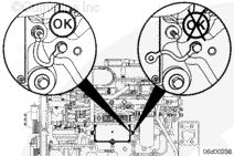
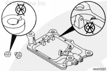
NOTE: Be sure the vibrations isolators are installed correctly. The isolators fit in a single direction into the chamfered locators.
Cycle the keyswitch and allow the lift pump to operate for 30 seconds. Afterwards, turn the keyswitch OFF and back ON again allowing the lift pump to operate again.
Allow the lift pump to operate for three or four 30-second cycles before attempting to start the engine.
Hello, I'm Jack, a diesel engine fan and a blogger. I write about how to fix and improve diesel engines, from cars to trucks to generators. I also review the newest models and innovations in the diesel market. If you are interested in learning more about diesel engines, check out my blog and leave your feedback.
View all posts by Jack


 WARNING
  CAUTION



;)
;)
;)
;)
;)
;)
;)
;)
;)
;)
;)
;)
