Obtain a 1.09 mm [0.043 in] orificed diagnostic fuel line, Part Number 3164621.
A 1.09 mm [0.043-inch] orificed diagnostic fuel line is used in procedures to create rated flow through the low pressure fuel system, without the need to operate the engine under load.
Obtain a container suitable for collection of fuel that exits the diagnostic fuel line (a 19 liter [5 gal] bucket is recommended).
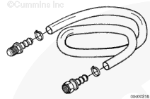
Construct a sight tube (CAPS) fuel systems only):
Assemble two (one male and one female, 7.8-14 thread barb-tite fittings and hose clamps to a 61 cm [2 ft] long number-10 clear hose approved for use with diesel fuel.
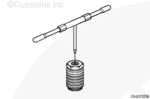
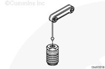
If 1.09 mm [0.043 in] orificed diagnostic fuel line, Part Number 3164621 can not be obtained, construct a 1.09 mm [0.043 in] orificed diagnostic fuel line, use the following steps:
Attach the orifice to an appropriate length (it must reach from the fuel pump to the fuel tank) of 1/4-inch, or larger, tubing.
NOTE: It is recommended that this tool be marked and identified as having a 1.09 mm [0.043 in] orifice installed. This is to make sure that there is no confusion when using this tool in the future.
NOTE: A symptom of air-in-fuel for the engines equipped with a common rail fuel system is an audible surge associated with fuel system pressure fluctuations, due to air in the fuel supply.
The following test method will simulate rated fuel flow through the system so that air in fuel problems may be diagnosed.
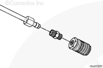
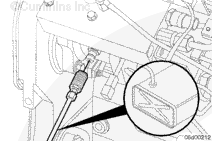
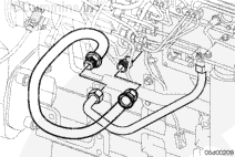
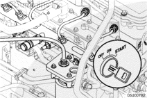
Install a Compuchek™ fitting, Part Number 3824842, at the inlet to the 2 micron fuel filter and attach the 1.09 mm [0.043 in] diagnostic fuel line.
NOTE: If there is not enough clearance to install the female Compuchek™ fitting, Part Number 3824842, an adapter fitting, Part Number 3932302, and an 1/8-NPT male Compuchek™ fitting, Part Number 3377244, can be used to aid accessibility.
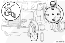
Route the outlet of the 1.09 mm [0.043-inch] diagnostic fuel line into a collection device of suitable size (a 19 liter [5 gal] bucket is recommended).
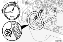
Start the engine and run the engine speed from idle to high idle several times to purge the air introduced while installing the diagnostic fuel line.
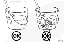
Observe the fuel flow exiting the diagnostic fuel line while the engine runs at idle speed.
Bubbles are an indication of a leak that allows air to enter, a severe inlet restriction that causes cavitation, or a system that is not yet primed. Refer to Procedure 006-020 Section 6.
Hello, I'm Jack, a diesel engine fan and a blogger. I write about how to fix and improve diesel engines, from cars to trucks to generators. I also review the newest models and innovations in the diesel market. If you are interested in learning more about diesel engines, check out my blog and leave your feedback.
View all posts by Jack
 WARNING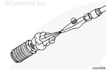




;)
;)
;)
;)
;)
;)
;)
;)
;)
;)
;)
;)
;)
;)
;)
;)
;)
;)
;)
;)
;)
;)
;)
;)