Batteries can emit explosive gases. To reduce the possibility of personal injury, always ventilate the compartment before servicing the batteries. To reduce the possibility of arcing, remove the negative (-) battery cable first and attach the negative (-) battery cable last.
Wear appropriate eye and face protection when using compressed air. Flying debris and dirt can cause personal injury.
WARNING
When using a steam cleaner, wear safety glasses or a face shield, as well as protective clothing. Hot steam can cause serious personal injury.
CAUTION
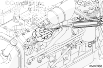
Clean all fittings before disassembly. Dirt or contaminants can damage the fuel system.
Before servicing any fuel system components, (such as fuel lines, fuel pump, injectors, etc.) which would expose the fuel system or internal engine component to potential contaminants prior to disassembly, clean the fittings, mounting hardware, and the area around the component to be removed. Dirt or contaminants can be introduced into the fuel system and engine if the surrounding areas are not cleaned, resulting in damage to the fuel system and engine. Refer to Procedure 000-009 in Section 0.
Fuel is flammable. Keep all cigarettes, flames, pilot lights, arcing equipment, and switches out of the work area and areas sharing ventilation to reduce the possibility of severe personal injury or death when working on the fuel system.
WARNING
Do not vent the fuel system on a hot engine; this can cause fuel to spill onto a hot exhaust manifold, which can cause a fire.
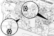
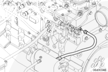
There are two drain lines on the engine:
The fuel injection pump drain line routes fuel from the fuel injection pump to the fuel lift pump drain manifold. This line has a p-clip brace that attaches to the cylinder head.
The injector drain line which routes fuel from the rear of the cylinder head to the fuel lift pump drain manifold.
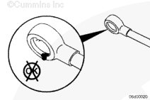
These lines are removed by removing the banjo bolts and sealing washers.
Fuel is flammable. Keep all cigarettes, flames, pilot lights, arcing equipment, and switches out of the work area and areas sharing ventilation to reduce the possibility of severe personal injury or death when working on the fuel system.
WARNING
Do not vent the fuel system on a hot engine; this can cause fuel to spill onto a hot exhaust manifold, which can cause a fire.
CAUTION
Use caution when disconnecting or removing fuel lines, replacing filters and priming the fuel system that fuel is not spilled or drained into the bilge area. Do not drop or throw filter elements into the bilge area. The fuel and fuel filters must be discarded in accordance with local environmental regulations.
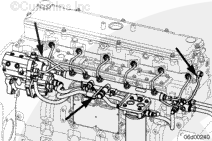
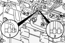
There are three drain lines on the engine:
The fuel pump drain line connects the fuel pump to the fuel drain manifold. This line has a p-clip brace that attaches to the engine cylinder head.
The fuel rail pressure relief valve drain line connects the fuel rail pressure relief valve to the fuel drain manifold.
The injector drain line connects the back of the cylinder head to the fuel drain manifold.
These lines are removed by removing the banjo bolts and sealing washers.
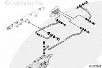
NOTE: QSL9 marine applications, which are keel cooled, do not have fuel coolers.
QSC8.3 and QSL9 marine applications, which are sea water cooled, have an additional drain line which transfers the fuel from the fuel drain manifold to the fuel cooler.
This line is removed by loosening the compression nuts.
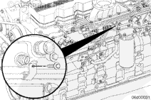
Connect the fuel drain line at the fuel pump banjo fitting at the rear of the cylinder head and at the lift pump. Use two (2) wrenches when installing the drain line at the fuel pump return.
Batteries can emit explosive gases. To reduce the possibility of personal injury, always ventilate the compartment before servicing the batteries. To reduce the possibility of arcing, remove the negative (-) battery cable first and attach the negative (-) battery cable last.
Connect the batteries. Refer to the OEM service manual.
Hello, I'm Jack, a diesel engine fan and a blogger. I write about how to fix and improve diesel engines, from cars to trucks to generators. I also review the newest models and innovations in the diesel market. If you are interested in learning more about diesel engines, check out my blog and leave your feedback.
View all posts by Jack

 WARNING


 CAUTION


;)
;)
;)
;)
;)
;)
;)
;)
;)
;)
;)
;)
;)
;)
;)
;)
;)
;)