ISC, ISCe, QSC8.3, ISL, ISLe3, ISLe4 and QSL9 Engines – 008-057   Sea Water Pump

Initial Check

TOC

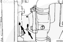
Inspect the sea water pump for evidence of water or oil, indicating seal leakage. If seal leakage is evident, the pump must be repaired or replaced.

SMALL | MEDIUM | LARGE


 CAUTION 

Zinc plugs expand and can break off during removal. Inspect the zinc plug to make sure it is in one piece. Refer to Procedure 008-059. If not, it must be replaced with a new zinc plug, and the broken pieces must be retrieved from the aftercooler to prevent damage to components downstream in the sea water system.

Shut off the sea water supply.

Drain the sea water pump by removing the zinc plug from the aftercooler on QSL engines. Refer to Procedure 010-005. On QSC engines, remove the plug at the bottom of the marine gear oil/fuel cooler assembly.

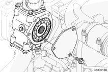
Remove the cover from the back of the sea water pump.

SMALL | MEDIUM | LARGE


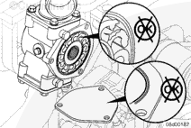
Inspect the cover for signs of grooves worn into the cover surface.

Inspect the impeller for missing, badly worn vanes, or chunks of vanes missing.

If the cover is badly grooved or the impeller is badly damaged, the pump must be repaired or replaced. See the Repair step in this procedure for replacing the sea water pump impeller without removing the pump from the engine.

If the impeller is damaged, the sea water circuit down stream (marine gear oil cooler, fuel cooler, aftercooler and aftercooler element) of the pump must be checked and cleaned.

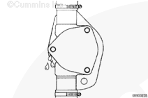
Inspect the cover o-ring for cuts or other damage.

SMALL | MEDIUM | LARGE


Install the cover on the back of the pump with the three mounting capscrews.

Torque Value:  24  n.m  [212 in-lb]

SMALL | MEDIUM | LARGE
   

Repair

TOC

 CAUTION 

If the impeller has failed and pieces are missing, all pieces must be retrieved. The engine heat exchanger, marine gear oil cooler, marine gear oil cooler and fuel cooler assembly, and sea water aftercooler must be flushed. Refer to procedures 008-053, 008-041, 008-129, and 010-005 for flushing these components. Failure to do so can result in overheating and damage to engine can occur.

Impeller debris can also drop into the inlet piping. Make sure all debris is removed before installing a new impeller; otherwise, additional impeller failures or engine overheating will occur.

SMALL | MEDIUM | LARGE


 CAUTION 

Zinc plugs expand and can break off during removal. Inspect the zinc plug to make sure it is in one piece. Refer to Procedure 008-059. If not, it must be replaced with a new zinc plug, and the broken pieces must be retrieved from the aftercooler to prevent damage to components downstream in the sea water system.

Shut off the sea water supply.

Drain the sea water pump by removing the zinc plug from the aftercooler on QSL engines. Refer to Procedure 010-005. On QSC engines, remove the plug at the bottom of the marine gear oil/fuel cooler assembly.

Remove the cover from the back of the sea water pump.

SMALL | MEDIUM | LARGE


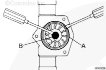
Use a small screwdriver to remove the o-ring (A).

Use a small screwdriver to remove the inner cap (B), if equipped.

Clean the o-ring groove.

SMALL | MEDIUM | LARGE


 CAUTION 

Do not pry against the pump housing to remove the impeller as this can cause damage to the liner.

Be sure to note the direction of impeller vanes for proper re-installation. Mark the outer surface.

An impeller removal tool is available from Sherwood Pumps, Part Number 23631.

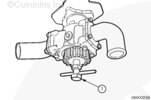
If the impeller is equipped with a threaded insert, use the special tool or a ¾-NFT bolt (1) to insert in the impeller to pull the impeller out.

SMALL | MEDIUM | LARGE


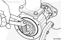
If the impeller does not have a threaded bore, grasp the hub of the impeller with pliers and remove the impeller from the impeller bore.

SMALL | MEDIUM | LARGE


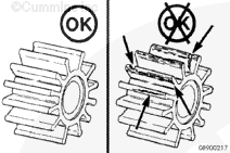
Inspect for damage such as rips, tears, chunks of material missing, or wear on the edges of the vanes.

Replace the impeller if damage is found.

SMALL | MEDIUM | LARGE


Clean the internal pump surfaces.

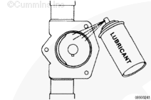
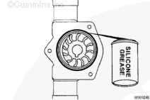
Lubricate the housing with silicone or glycerine non-petroleum-based lubricant. Petroleum-based lubricant will damage the rubber impeller.

If non-petroleum-based lubricant is not readily available, use soapy water to ease installation.

SMALL | MEDIUM | LARGE


If the impeller is in good shape and will be reused, install it in the same direction from which it was removed. See the mark you made during removal.

If the impeller was not marked and the original rotation or direction can not be determined, replace the impeller with a new one.

SMALL | MEDIUM | LARGE


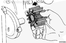
An oil filter strap wrench or even plastic wire straps can be used as an installation aid to hold the vanes.

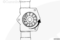
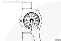
Guide the impeller into the housing, twisting it counterclockwise as it is advanced so that the vanes will be deflected in the proper direction.

SMALL | MEDIUM | LARGE


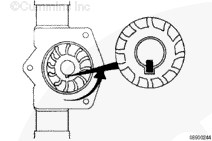
Continue to turn the impeller while pushing it into the housing. It will slide all the way in when the keyway lines up with the key.

SMALL | MEDIUM | LARGE


Insert the new o-ring into the impeller housing. Use a light coat of silicone grease to hold the o-ring in place.

SMALL | MEDIUM | LARGE


Install the rubber impeller cap into the center hub of the impeller, if equipped.

SMALL | MEDIUM | LARGE


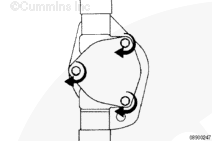
Install the cover plate and capscrews.

Tighten the capscrews.

Torque Value:  24  n.m  [212 in-lb]

SMALL | MEDIUM | LARGE
   

Preparatory Steps

TOC

 CAUTION 

Zinc plugs expand and can break off during removal. Inspect the zinc plug to make sure it is in one piece. If not, it must be replaced with a new zinc plug, and the broken pieces must be retrieved from the aftercooler to prevent damage to components downstream in the sea water system.
  • Shut off the sea water supply. Refer to the OEM service manual.
  • Drain the sea water system by removing the zinc plug from the bottom of the aftercooler of QSL engines. Refer to Procedure 010-005. On QSC engines, remove the plug at the bottom of the marine gear oil/fuel cooler assembly.
 
SMALL | MEDIUM | LARGE
   

Remove

TOC

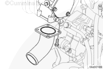
Remove the upper and lower water connections from the sea water pump.

Remove the o-rings.

SMALL | MEDIUM | LARGE


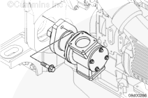
Remove the sea water pump mounting capscrews.

Remove the sea water pump.

SMALL | MEDIUM | LARGE
   

Inspect for Reuse

TOC

Inspect the pump for cracks, leakage points or other exterior damage.

Remove the rear cover and inspect the impeller.

Repair or replace the sea water pump if damage is found.

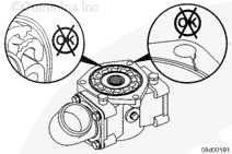
Inspect the water inlet and outlet connection o-rings. Replace if damaged.

SMALL | MEDIUM | LARGE
   

Install

TOC

NOTE: If a new sea water pump is being installed, the sea water pump must be painted before installation.

Install the sea water pump.

Install the sea water pump mounting capscrews and tighten.

Torque Value:  24  n.m  [18 ft-lb]

SMALL | MEDIUM | LARGE


Install the o-rings onto the water inlet and outlet connections. Use a light coat of silicone grease to hold the o-rings in place.

Install the upper and lower water connections from the sea water pump.

Install the capscrews and tighten.

Torque Value:  133  n.m  [15 in-lb]

SMALL | MEDIUM | LARGE
   

Finishing Steps

TOC

  • Install the zinc plug in the aftercooler on QSL engines. Refer to Procedure 010-005. On QSC engines, install the plug in the bottom of the marine gear oil/fuel cooler assembly.
  • Open the sea water supply.

Operate the engine and check for leaks.

 
SMALL | MEDIUM | LARGE
Last Modified:  22-Jul-2005