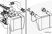
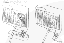
To reduce the possibility of injury if either plug blows off during the test, secure safety chains on the test plugs to any convenient capscrew on the radiator assembly. This test must be performed with securely fastened safety chains.
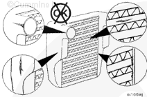
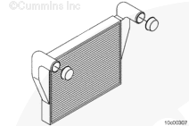
To check the charge-air cooler for cracked tubes or header, remove the inlet and outlet hoses from the cooler. The charge-air cooler does not have to be removed from the chassis.
Use protective caps from the Air Handling Clean Care Kit, Part Number 4919508, to cover open points on the plumbing, engine, and charge-air cooler.
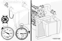
Determine if the pressure drop is caused by a leak in the charge-air cooler or by a leaky connection. Use a spray bottle filled with soapy water, applied to all hose connections. Watch for bubbles to appear at the location of the leak.
If the pressure drop is caused by a leaky connection, repair the connection, and repeat the test. If the leak is within the charge-air cooler, repeat the test to verify the accuracy of the pressure drop measurement. Similar pressure drop readings must be obtained at least three consecutive tests before the reading can be considered accurate.
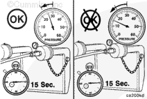
NOTE: If a charge-air cooler leak causes a pressure drop of more than 48 kPa [7 psi] in 15 seconds, it will appear as a major leak in a leak tank.
If the pressure drop is greater than 48 kPa [7 psi] in 15 seconds, the charge air cooler must be replaced.
Refer to the OEM service manual for replacement instructions.
NOTE: Charge-air coolers are not designed to be 100-percent leak-free. If the pressure drop is less than 48 kPa [7 psi] in 15 seconds, the charge-air cooler does not need to be replaced.
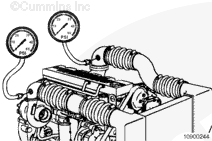
Obtain two pressure gauges, Part Number 3823205. Check both gauges on the same pressure source at 206 kPa [30 psi] to verify consistency.
Install one pressure gauge in the 1/8-inch fitting in the turbocharger compressor outlet elbow. Install the other pressure gauge in the intake manifold.
Another alternative to measure the intake manifold pressure is to use the monitor mode on INSITE™ electronic service tool.
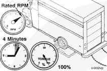
Operate the engine at rated rpm and load. Record the readings on the two gauges.
If the differential pressure is greater than 20.6 kPa [3 psi], check the charge air cooler and associated piping for plugging, restrictions, or damage.
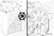
Inspect the charge-air cooler fins for obstructions to air flow. Remove obstructions such as a winterfront or debris. Manually lock the shutters in the OPEN position, if equipped.
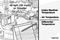
Lock the fan drive in the ON mode to prevent erratic test results. This can be done by installing a jumper wire across the temperature switch.
Install fluke digital thermometer, Part Number 3822666, into the intake manifold at the 1/8-inch NPT tap near the air horn connection with the intake manifold.
Install the thermocouple bead probe, Part Number 3164498.
Connect the digital multimeter, Part Number 3164488, and the temperature adaptor, Part Number 3164499, to the thermocouple bead probe to read intake air temperature.
Another alternative is to use the monitor mode on the INSITE™ electronic service tool.
Install another thermocouple at the air cleaner inlet to measure ambient air temperature.
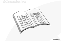
If the temperature differential is greater than the specifications, check the charge-air cooler for dirt and debris on the fins and clean as necessary. If the problem still exists, check the charge-air cooler for debris in the fins or between the charge-air cooler and radiator. Confirm full fan engagement.
When using solvents, acids, or alkaline materials for cleaning, follow the manufacturer’s recommendations for use. Wear goggles and protective clothing to reduce the possibility of personal injury.
CAUTION
Do not use caustic cleaners to clean the charge-air cooler. Damage to the charge-air cooler will result.
NOTE: If the engine experiences a turbocharger failure or any other occasion where oil or debris is put into the charge-air cooler, the charge-air cooler must be cleaned.
Flush the charge-air cooler internally with solvent in the opposite direction of normal airflow. Shake the charge-air cooler, and lightly tap on the end tanks with a rubber mallet to dislodge trapped debris. Continue flushing until all debris or oil is removed (i.e., the water runs clear).
NOTE: Make sure that the tubes are in the upright position when flushing.
If the debris can not be totally removed from the charge-air cooler, the charge air cooler must be replaced.
Wear appropriate eye and face protection when using compressed air. Flying debris and dirt can cause personal injury.
CAUTION
The charge-air cooler must be rinsed, dried, and free of solvent, oil, and debris, or engine damage will result.
After the charge-air cooler has been thoroughly cleaned of all oil and debris with solvent, wash the charge-air cooler internally with hot soapy water to remove the remaining solvent. Rinse thoroughly with clean water.
Blow compressed air through the inside of the charge-air cooler in the opposite direction of normal air flow until the charge-air cooler is dry internally.
Hello, I'm Jack, a diesel engine fan and a blogger. I write about how to fix and improve diesel engines, from cars to trucks to generators. I also review the newest models and innovations in the diesel market. If you are interested in learning more about diesel engines, check out my blog and leave your feedback.
View all posts by Jack

 WARNING






 CAUTION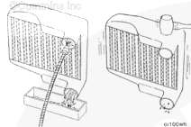
;)
;)
;)
;)
;)
;)
;)
;)
;)
;)
;)
;)
;)
;)
;)
;)
;)
;)
;)
;)
;)
;)
;)
;)
;)
;)
;)
;)
;)
;)
