Batteries can emit explosive gases. To reduce the possibility of personal injury, always ventilate the compartment before servicing the batteries. To reduce the possibility of arcing, remove the negative (-) battery cable first and attach the negative (-) battery cable last.
Check the battery and all wiring connections.
Inspect the wiring for defects.
Check all connections for tightness and cleanliness, including the slip connectors at the alternator and engine compartment bulkhead, and connections at the battery.
Digital Multimeter, Part Number 3164488; Clamp-on Current Probe, Part Number 3823574:
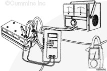
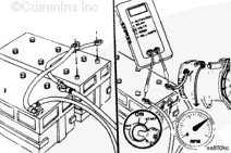
Connect a carbon pile load (battery tester) across the battery posts of the battery boxes.
Clamp an induction pickup type amp meter around the battery cable, or use the digital multimeter, Cummins® Part Number 3164488, with the clamp-on current probe, Cummins® Part Number 3823574.
Disconnect any cables that lead to any other battery boxes in the circuit, negative (-) cables first.
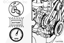
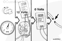
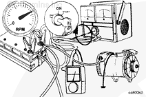
Operate the engine at high idle and measure the alternator voltage output to the batteries with digital multimeter, Part Number 3164488. See the alternator manufacturer’s specifications.
Operate the engine at high idle and adjust the systems analyzer/battery tester to apply the maximum rated amperage load to the alternator. See the alternator manufacturer’s specifications.
NOTE: The alternator maximum rated amperage output is normally stamped or labeled on the alternator.
Measure the alternator amperage output. See the alternator manufacturer’s specifications.
If the gauge on the carbon pile load testing equipment does not indicate approximately the same output as the induction-type ampmeter, determine which is defective and replace it. See the alternator manufacturer’s specifications.
If the alternator output (amps) is not within 10 percent of rated output, repair or replace the alternator. See the alternator manufacturer’s instructions for repair procedures.
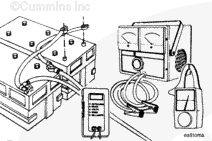
Connect a carbon-pile load (battery/alternator tester) across the battery posts of the battery boxes.
Clamp an induction pickup-type ampere-hour meter around the battery cable; or use the digital multimeter, Part Number 3164488 or 3164489, with the clamp-on current probe, Part Number 3164490.
Batteries can emit explosive gases. To reduce the possibility of personal injury, always ventilate the compartment before servicing the batteries. To reduce the possibility of arcing, remove the negative (-) battery cable first and attach the negative (-) battery cable last.
WARNING
Acid is extremely dangerous and can damage the machinery and can also cause serious burns. Always provide a tank of strong soda water as a neutralizing agent when servicing the batteries. Wear goggles and protective clothing to reduce the possibility of serious personal injury.
Disconnect any cables that lead to any other battery boxes in the circuit, negative (-) cables first.
Operate the engine at high idle; and measure the alternator voltage output to the batteries with digital multimeter, Part Number 3164488 or 3164489. Refer to the OEM specifications.
Operate the engine at high idle and adjust the carbon-pile load-testing equipment to apply the maximum rated amperage load to the alternator. Refer to the OEM specifications.
NOTE: The alternator maximum rated amperage output is normally stamped or labeled on the alternator.
Measure the alternator amperage output. Refer to the OEM specifications.
If the alternator output (amps) is not within 10 percent of rated output, repair or replace the alternator. Refer to the OEM service manual for repair procedures.
Batteries can emit explosive gases. To reduce the possibility of personal injury, always ventilate the compartment before servicing the batteries. To reduce the possibility of arcing, remove the negative (-) battery cable first and attach the negative (-) battery cable last.
WARNING
Acid is extremely dangerous and can damage the machinery and can also cause serious burns. Always provide a tank of strong soda water as a neutralizing agent when servicing the batteries. Wear goggles and protective clothing to reduce the possibility of serious personal injury.
Shut off the engine and remove the test equipment.
Connect all battery cables, negative (-) cable last.
Batteries can emit explosive gases. To reduce the possibility of personal injury, always ventilate the compartment before servicing the batteries. To reduce the possibility of arcing, remove the negative (-) battery cable first and attach the negative (-) battery cable last.
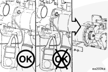
Remove and tag all wires and complete the following steps:
Batteries can emit explosive gases. To reduce the possibility of personal injury, always ventilate the compartment before servicing the batteries. To reduce the possibility of arcing, remove the negative (-) battery cable first and attach the negative (-) battery cable last.
Hello, I'm Jack, a diesel engine fan and a blogger. I write about how to fix and improve diesel engines, from cars to trucks to generators. I also review the newest models and innovations in the diesel market. If you are interested in learning more about diesel engines, check out my blog and leave your feedback.
View all posts by Jack

 WARNING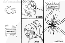





;)
;)
;)
;)
;)
;)
;)
;)
;)
;)
;)
;)
;)
;)
;)
;)
;)
;)
;)
;)
;)
;)
