The injector solenoids receive high voltage when the engine is operating. To avoid personal injury or death from electrical shock, do not wear jewelry or damp clothing, and do not touch the injector solenoids or the solenoid wires when the engine is operating.
CAUTION
Do not use probes or leads other than Part Number 3822758. The connector will be damaged. The leads must fit tightly in the connector without expanding the connector pins.
Inspect the injector solenoid circuit of the cylinder referenced on the recorded fault code. Refer to the wiring diagram for connector pin identification. Cylinder number 1 will be used as an example.
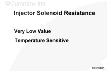
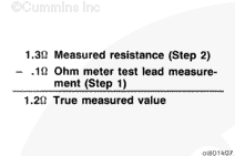
The resistance value of the injector solenoid circuit is very low. The solenoid resistance is also temperature sensitive. To read an accurate resistance value, the resistance of the multimeter must be subtracted from the total resistance of the injector solenoid circuit.
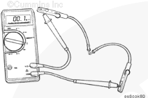
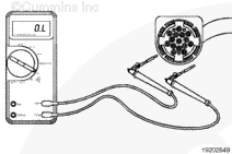
Use a multimeter for this procedure. Use Cummins multimeter, Part Number 3164489, or a meter with the same accuracy of ±1/2 percent.
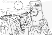
Turn the multimeter on. Set the meter range to the lowest ohm scale. Measure the resistance across the two test probes. This is the multimeter resistance value which will be subtracted from the injector solenoid resistance value.
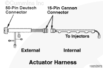
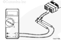
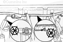
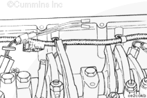
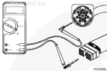
Disconnect the actuator harness connector from the fuel control module.
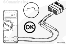
Insert a test lead into cylinder number 1 injector solenoid signal pin of the actuator harness connector. Insert the other lead into cylinder number 1 injector solenoid return pin of the actuator harness connector.
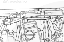
Measure the resistance. Subtract the multimeter test lead resistance value from this value to determine the true injector circuit resistance value. The resistance must be 0.5 to 1.5 ohms. If the resistance value is not correct, proceed with the following sections. If the resistance is correct, the circuit must still be checked for a short circuit to ground and a short circuit from pin to pin.
NOTE: If the resistance measurement is less than 10 ohms, the circuit is acceptable as long as the resistance of the injector solenoid is within 0.5 to 1.5 ohms (see Resistance Value Above Specification).
Measure the resistance between the two posts or the connection of the injector solenoid. Subtract the multimeter resistance. The true injector solenoid resistance must be 0.5 to 1.5 ohms. If the resistance value is not correct, replace the injector. Refer to Procedure 006-026 in the ISM, ISMe, and QSM11 Service Manual, Bulletin 3666322, or the Signature, ISX and QSX15 Service Manual, Bulletin 3666239.
If the resistance value of the injector solenoid is correct, the problem is in the internal or external actuator harness. Isolate the problem by checking each harness separately.
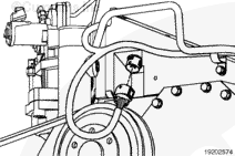
Disconnect the 15-pin actuator harness connector at the front of the rocker lever housing.
Check the internal actuator harness. Measure the resistance between the two captive nut assemblies, or the connection, of the injector solenoid wire that was removed from the injector solenoid. The resistance must be an open circuit (more than 100k ohms). If the resistance is less than 100k ohms, replace the internal actuator wiring harness. Refer to Procedure 019-063. Do not repair the internal actuator harness.
Connect the 15-pin connector when the repair is completed.
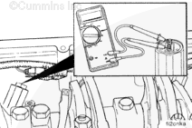
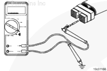
Check the external actuator harness. Make sure that the 15-pin connector is still disconnected. Insert a test lead into cylinder number 1 injector solenoid signal pin of the actuator harness connector. Insert the other lead into cylinder number 1 injector solenoid return pin of the actuator harness connector.
Measure the resistance. The circuit must be an open (more than 100k ohms). If the resistance is less than 100k ohms, repair or replace the external actuator harness. Refer to Procedure 019-043.
Connect the 15-pin connector when the repair is completed.
Inspect the injector solenoid wires for broken wires. If the wires are damaged, replace the wires. Refer to Procedure 019-057. Do not repair the wires.
Check the 15-pin connector for a tight connection.
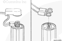
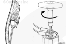
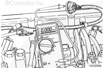
Check for an open circuit in the injector solenoid. Use a small screwdriver to remove the protective cover from the solenoid. Remove the captive nut assembly from the injector solenoid.
Measure the resistance between the posts or the connection of the injector solenoid. Subtract the multimeter resistance. The true injector solenoid resistance must be 0.5 to 1.5 ohms. If the resistance is not correct, replace the injector. Refer to Procedure 006-026 in the ISM, ISMe, and QSM11 Service Manual, Bulletin 3666322, or the Signature, ISX and QSX15 Service Manual, Bulletin 3666239.
Do not use probes or leads other than the mating connector. The connector will be damaged. The leads must fit tightly in the connector without expanding the connector pins.
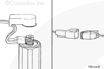
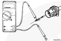
Connect a mating connector with short lead extensions to the injector side of the 2-pin connector.
Touch one multimeter probe to the end of the short lead extension. Touch the other multimeter probe to the captive nut assembly of the injector solenoid wire. Measure the resistance. Repeat the procedure for the other injector wire. The resistance for both of these checks must be less than 10 ohms. If the resistance is more than 10 ohms, replace the injector solenoid wires. Refer to Procedure 019-057. Do not repair the wires.
Check the injector solenoid signal wire for an open circuit. Refer to the wiring diagram for connector pin identification. Cylinder number 1 will be used as an example.
Touch one multimeter probe to cylinder number 1 injector solenoid signal pin at the injector 2-pin connector, internal actuator harness side.
Touch the other multimeter probe to cylinder number 1 injector solenoid signal pin at the 15-pin connector, internal actuator harness side. Measure the resistance. The resistance must be less than 10 ohms. If more than 10 ohms are measured, replace the internal actuator harness. Refer to Procedure 019-063. Do not repair the wire.
Check the injector solenoid return wire for an open circuit. Touch a multimeter probe to cylinder number 1 injector solenoid return pin at the injector 2-pin connector, internal actuator harness side. Touch another multimeter probe on cylinder number 1 injector solenoid return pin of the 15-pin connector, internal actuator harness side.
Measure the resistance. The resistance must be less than 10 ohms. If more than 10 ohms are measured, replace the internal actuator harness. Refer to Procedure 019-063. Do not repair the wires.
Connect the 15-pin connector when the repair is completed.
Check the external actuator harness for an open circuit. Refer to the wiring diagram for connector pin identification. Cylinder number 1 will be used as an example.
Insert a test lead into cylinder number 1 injector solenoid signal pin of the actuator harness.
Insert the other multimeter probe on cylinder number 1 injector solenoid signal pin at the 15-pin connector, external actuator harness side. Measure the resistance. The resistance must be less than 10 ohms. If more than 10 ohms are measured, repair the wire or replace the actuator harness. Refer to Procedure 019-043.
Insert a test lead into cylinder number 1 injector solenoid return pin of the actuator harness connector. Place the other multimeter probe on cylinder number 1 injector solenoid return pin at the 15-pin connector, external harness side.
Measure the resistance. The resistance must be less than 10 ohms. If more than 10 ohms are measured, repair the return wire or replace the actuator harness. Refer to Procedure 019-043.
Connect the 15-pin connector when the repair is completed.
The injector solenoids receive high voltage when the engine is operating. To avoid personal injury or death from electrical shock, do not wear jewelry or damp clothing, and do not touch the injector solenoids or the solenoid wires when the engine is operating.
Check for a short circuit to ground in the external actuator harness. Refer to the wiring diagram for connector pin identification. Cylinder number 1 will be used as an example.
Turn the vehicle keyswitch to the OFF position. Disconnect the actuator harness connector from the fuel control module.
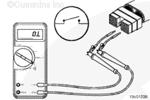
Insert a test lead into cylinder number 1 injector solenoid signal pin of the actuator harness connector. Touch the other multimeter probe to engine block ground. Measure the resistance.
The circuit must be open (100k ohms or more). If it is not open, isolate the short to the external or internal actuator harness.
With the actuator harness still disconnected from the fuel control module, disconnect the actuator harness from the 15-pin connector.
Insert a test lead into cylinder number 1 injector solenoid signal pin of the 15-pin connector, internal actuator harness side. Touch the other multimeter probe to engine block ground. Measure the resistance.
The circuit must be open (100k ohms or more). If it is not open, the short circuit is in the internal actuator harness side. Replace the internal actuator harness. Refer to Procedure 019-063. If the circuit is open, then repair or replace the external harness. Refer to Procedure 019-043.
The injector solenoids receive high voltage when the engine is operating. To avoid personal injury or death from electrical shock, do not wear jewelry or damp clothing, and do not touch the injector solenoids or the solenoid wires when the engine is operating.
Check for a short circuit from pin to pin. Refer to the wiring diagram for connector pin identification. Cylinder number 1 will be used as an example.
Turn the vehicle keyswitch to the OFF position. Disconnect the actuator and sensor harness connectors from the fuel control module. Disconnect the actuator harness from the 15-pin connector.
Insert a test lead into cylinder number 1 injector solenoid signal pin of the actuator harness connector. Insert the other test lead into all other pins of the actuator harness connector, one at a time. Measure the resistance.
Repeat same check as previous from cylinder number 1 injector solenoid return pin. The circuit must be open (100k ohms or more) at all pins. If the circuit is not open, repair or replace the actuator harness. Refer to Procedure 019-043.
Insert a test lead into cylinder number 1 injector solenoid signal pin of the actuator harness connector. Insert the other test lead into all other pins of the sensor harness connector, one at a time. Measure the resistance.
Repeat the same check as previous from cylinder number 1 injector solenoid return pin. The circuit must be open (100k ohms or more) at all pins. If the circuit is not open, repair or replace the actuator or sensor harness. Refer to Procedure 019-043.
Check for a short circuit from pin to pin in the 15-pin connector. Disconnect the internal harness from the injector solenoid.
Insert a test lead into cylinder number 1 injector solenoid signal pin of the 15-pin pass-through connector, internal harness side. Insert the other test lead into all other pins of the 15-pin connector, one at a time. Measure the resistance.
The circuit must be open (100k ohms or more). If it is not open, replace the internal actuator harness. Refer to Procedure 019-063.
Insert a test lead into cylinder number 1 injector solenoid return pin of the 15-pin connector, internal harness side. Insert the other test lead into all other pins of the 15-pin connector, one at a time. Measure the resistance.
The circuit must be open (100k ohms or more). If it is not open, replace the internal actuator harness. Refer to Procedure 019-063.
Connect all components after completing the repair.
Hello, I'm Jack, a diesel engine fan and a blogger. I write about how to fix and improve diesel engines, from cars to trucks to generators. I also review the newest models and innovations in the diesel market. If you are interested in learning more about diesel engines, check out my blog and leave your feedback.
View all posts by Jack

 WARNING
  CAUTION


;)
;)
;)
;)
;)
;)
;)
;)
;)
;)
;)
;)
;)
;)
;)
;)
;)
;)
;)
;)
;)
;)
;)
;)
;)
;)
;)
;)
;)
;)
;)
;)
;)
;)
;)
;)
;)
;)
;)
;)
;)
;)