 |
Engine Performance Troubleshooting Tree – ISX CM871

Symptoms
- Engine Acceleration or Response Poor
- Cranking Fuel Pressure is Low
- Engine Operating Fuel Pressure is Low
- Engine Difficult to Start or Will Not Start (Exhaust Smoke)
- Engine Difficult to Start or Will Not Start (No Exhaust Smoke)
- Engine Power Output Low
- Engine Runs Rough at Idle
- Engine Runs Rough or Misfires
- Engine Speed Surges at Low or High Idle
- Engine Speed Surges Under Load or in Operating Range
- Smoke, Black – Excessive
- Smoke, White – Excessive
- Engine Shuts Off or Dies Unexpectedly or Dies During Deceleration
- Engine Starts But Will Not Keep Operating
- Engine Will Not Reach Rated Speed (rpm)
- Engine Run-on or Will Not Shut Down.
How To Use This Tree
This symptom tree can be used to troubleshoot all performance-based symptoms listed above. Start by performing Step 1 troubleshooting. Step 2 asks a series of questions and will provide a list of troubleshooting steps to perform, depending on the symptom. Perform the list of troubleshooting in the sequence shown in the Specifications/Repair section of the tree.
Shop Talk
Verify the electronic control module (ECM) calibration is correct. Check the calibration revision history found on QuickServe™ Online for applicable fixes to the calibration stored in the ECM. If necessary, calibrate the ECM. Use the following procedure in the Troubleshooting and Repair Manual, CM871 and CM876 Electronic Control Systems, ISX and ISM Engines, Bulletin 4021560. Refer to Procedure 019-032 in Section 19.
Troubleshooting Steps
| STEPS | SPECIFICATIONS | |
|---|---|---|
| STEP 1. | Perform basic troubleshooting procedures. | |
| STEP 1A. Check for active fault codes or high counts of inactive fault codes. | Active fault codes or high counts of inactive fault codes? | |
| STEP 1B. Perform basic troubleshooting checks. | All steps verified to be correct? | |
| STEP 1C. Perform INSITE™ electronic service tool monitor test. | ‘Engine Operating State’ reading a value that can cause an engine derate? | |
| STEP 2. | Determination of engine symptom. | |
| STEP 2A. Low power, poor acceleration, or poor response. | Engine symptom – Low Power, Poor Acceleration, or Poor Response? | |
| STEP 2B. Engine misfire. | Engins symptom – Engine Misfires | |
| STEP 2C. Excessive black smoke. | Engine symptom – Excessive Black Smoke? | |
| STEP 2D. Excessive white smoke. | Engine symptom – Excessive White Smoke and the Engine is Using Coolant? | |
| STEP 2D-1. Excessive white smoke. | ||
| STEP 2E. Engine speed surge or engine speed unstable. | Engine symptom – Engine Speed Surge or Engine Speed Unstable? | |
| STEP 2F. Engine will not start or difficult to start. | Engine symptom – Engine Difficult to Start or Will Not Start? | |
| STEP 2G. Engine stalls or shuts off unexpectedly. | Engine symptom – Engine Stalls or Shuts Off Unexpectedly? | |
| STEP 2H. Engine run-on or will not shut down. | Engine symptom – Engine Run-On or Slow to Shut Down after operating at high idle for 1 minute then keyed OFF? | |
| STEP 3. | No-start troubleshooting procedures. | |
| STEP 3A. Verify the fuel system has been primed. | Fuel system been properly primed? | |
| STEP 3B. Check fuel shutoff valve voltage. | Fuel shutoff valve voltage greater than 11-VDC? | |
| STEP 3B-1. Check the keyswitch voltage. | ||
| STEP 3B-2. Check the fuel shutoff valve wire. | ||
| STEP 3B-3. Check the ECM power and ground. | ||
| STEP 3C. Check fuel shutoff valve resistance. | Fuel shutoff solenoid resistance: 1 to 5 ohms for 6-VDC solenoids; 6 to 15 ohms for 12-VDC solenoids; 24 to 50 ohms for 24-VDC solenoids; 42 to 80 ohms for 32-VDC solenoids; 46 to 87 ohms for 36-VDC solenoids; 92 to 145 ohms for 48-VDC solenoids; 315 to 375 ohms for 74-VDC solenoids; or 645 to 735 ohms for 115-VAC solenoids? | |
| STEP 3D. Check the fuel shutoff valve actuator. | Debris or damage found on the valve disc, valve seat, or actuator disc? | |
| STEP 3E. Check for correct priming pump operation, if equipped. | Lift pump operates after turning the keyswitch ON? | |
| STEP 3E-1. Check priming pump pressure. | ||
| STEP 3F. Check for coolant in the EGR transfer tube. | Coolant present in the crossover tube? | |
| STEP 4. | Fuel system checks. | |
| STEP 4A. Verify the fuel system has been primed. | Fuel system properly primed? | |
| STEP 4B. Check for air in the fuel. | Air bubbles visible in the coil of clear tubing? | |
| STEP 4C. Check for fuel inlet restriction. | Fuel inlet restriction less than the specifications listed? Dirty – 305 mm-Hg [12 in-Hg]; New – 203 mm-Hg [8 in-Hg] | |
| STEP 4D. Check for drain line restriction. | Fuel drain line restriction less than 229 mm-Hg [9 in-Hg]? | |
| STEP 4E. Check rail fuel pressure. | Rail fuel pressure meets the specification? | |
| STEP 4E-1. Check the pressure side fuel filter restriction | ||
| STEP 4E-2. Check 1724 kPa [250 psi] pressure regulator. | ||
| STEP 4E-3. Check 2206 kPa [320 psi] or 2620 kPa [380 psi] pressure regulator. | ||
| STEP 5. | Injector and Actuator Diagnostics. | |
| STEP 5A. Perform the injector check valve leak test. | Injector leak test detects a leaking injector? | |
| STEP 5B. Perform INSITE™ electronic service tool Cylinder Performance Test. | INSITE™ electronic service tool Cylinder Performance Test identifies a single malfunctioning injector? | |
| STEP 5B-1. Perform INSITE™ electronic service tool Cylinder Performance Test at 600 rpm. | ||
| STEP 5B-2. Perform INSITE™ electronic service tool Cylinder Performance Test at 700 rpm. | ||
| STEP 5B-3. Perform INSITE™ electronic service tool Cylinder Performance Test at 800 rpm. | ||
| STEP 5C. Perform INSITE™ electronic service tool Cylinder Cutout Test. | Cylinders pass the cylinder cutout test? | |
| STEP 5C-1. Perform INSITE™ electronic service tool Cylinder Cutout Test on both injector banks. | ||
| STEP 5C-2. Perform INSITE™ electronic service tool Cylinder Cutout Test. | ||
| STEP 5C-3. Verify overhead adjustments are correct for the suspected malfunctioning injector. | ||
| STEP 5D. Swap the front and rear metering actuators. | Cylinder performance test finds a malfunctioning bank? | |
| STEP 5E. Swap the front and rear timing actuators. | Malfunctioning bank follows the timing actuator? | |
| STEP 5F. Monitor the engine percent load value with INSITE™ electronic service tool. (Perform this step for troubleshooting low power only.) | Engine percent load value consistently above 8 percent? | |
| STEP 6. | Air handling diagnostic checks. | |
| STEP 6A. Start the engine and read the fault codes. | Active fault codes? | |
| STEP 6B. Check air intake restriction. | Air intake restriction greater than 635 mm-H2O [25 in-H2O] for a used air filter or 254 mm-H2O [10 in-H2O] for a new filter? | |
| STEP 6C. Inspect the charge-air cooler. | Pressure drop 34 kPa [5 psi] or less in 15 seconds? | |
| STEP 6D. Inspect the turbocharger blades for damage. | Damage found on turbocharger blades? | |
| STEP 6E. Inspect the turbocharger shaft movement. | Nozzle slides evenly from stop to stop and gear teeth undamaged? | |
| STEP 7. | Check EGR valve for proper operation. | |
| STEP 7A. Check for EGR-related fault codes. | EGR-related fault codes present? | |
| STEP 7B. Check for inactive EGR differential pressure sensor fault codes. | Fault Code 1866, 2273, or 2274 active? | |
| STEP 7C. Check the EGR differential pressure tubes for leaks. | Leaks detected at either the low or high EGR differential pressure tubes? | |
| STEP 7D. Check the EGR differential pressure sensor adapter for leaks. | Leaks detected at the EGR differential pressure sensor adapter? | |
| STEP 7E. Check the EGR differential pressure tubes for plugging. | Debris or soot found in either EGR differential pressure tube? | |
| STEP 7F. Check for air leaks in the EGR system. | Leaks found in the EGR connection tubing? | |
| STEP 8. | Verify electronic features are operating correctly. | |
| STEP 8A. Verify accelerator pedal travel. | Accelerator pedal reads 0 when the accelerator is released and 100 percent when the accelerator is depressed? | |
| STEP 8B. Monitor vehicle speed. | Vehicle speed reads 0 when the vehicle is not moving? | |
| STEP 8C. Verify electronic feature settings are correct. | Electronic features set correctly? | |
| STEP 8D. Check the ambient air pressure sensor accuracy. | Barometric pressure sensor reading in INSITE™ electronic service tool within 5 percent of the present local barometric pressure reading? | |
| STEP 8E. Check the intake manifold pressure sensor accuracy. | INSITE™ electronic service tool reading within 17 kPa [2.5 psi] of mechanical gauge reading? | |
| STEP 9. | Perform base engine mechanical checks. | |
| STEP 9A. Verify injection timing is correct. | Injection timing correct? | |
| STEP 9B. Verify overhead adjustments are correct. | Overhead settings within the reset limits? | |
| STEP 9C. Verify engine brake adjustment. | Engine brake settings within the reset limits? | |
| STEP 9D. Verify crankshaft tone wheel is not loose. | Crankshaft tone wheel loose? | |
| STEP 9E. Check exhaust restriction. | Exhaust restriction greater than 305 mm-Hg [12.0 in-Hg]? | |
| STEP 9F. Verify engine blowby is within specification. | Engine blowby measurements within specification? | |
| STEP 10. | Aftertreatment checks. | |
| STEP 10A. Check for aftertreatment-related fault codes. | Fault codes related to the aftertreatment system found to be active? | |
| STEP 10B. Perform basic aftertreatment troubleshooting checks. | All parts inspected and appear to be functioning properly? | |
| STEP 10C. Check for signs of internal damage to the aftertreatment system. | Any visible smoke (black or white) present during the snap throttle acceleration? | |
| STEP 10D. Check exhaust restriction. | Exhaust restriction greater than 305 mm-Hg [12.0 in-Hg]? | |
Guided Step 1 – Perform basic troubleshooting procedures.
| Guided Step 1A – Check for active fault codes or high counts of inactive fault codes. | |
|---|---|
Conditions
ActionCheck for active fault codes or high counts of inactive fault codes.
|
|
|
Active fault codes or high counts of inactive fault codes? |
|
| YES | NO |
| No Repair | No Repair |
|
Go to appropriate fault code troubleshooting tree
|
|
| Guided Step 1B – Perform basic troubleshooting checks. | |
|---|---|
ConditionsN/A ActionThe following items must be checked or verified before continuing:
|
|
|
All steps verified to be correct? |
|
| YES | NO |
| No Repair |
Correct the out-of-specification item and verify complaint is no longer present after repair. |
|
Repair complete
|
|
| Guided Step 1C – Perform INSITE™ electronic service tool monitor test. | |
|---|---|
Conditions
ActionUse INSITE™ electronic service tool to monitor the parameter ‘Engine Operating State’ at the same engine operating conditions where the symptom occurs. Refer to Advanced Engine Performance Troubleshooting Techniques, Bulletin 4021686, for a description of what “User Fueling States (Engine Operating States)” can cause engine derates. |
|
|
‘Engine Operating State’ reading a value that can cause an engine derate? |
|
| YES | NO |
|
Determine if the engine derate is being caused by normal engine operation or by actual engine damage. Continue following troubleshooting steps as outlined in Step 2 if an engine failure is suspected. |
No Repair |
Guided Step 2 – Determination of engine symptom.
| Guided Step 2A – Low power, poor acceleration, or poor response. | |
|---|---|
ActionInterview the driver and verify the complaint. |
|
|
Engine symptom Low Power, Poor Acceleration, or Poor Response? |
|
| YES | NO |
|
Perform the troubleshooting steps in the recommended order listed below:
|
No Repair |
|
Perform the troubleshooting steps suggested in the repair procedure
|
|
| Guided Step 2B – Engine misfire. | |
|---|---|
ActionInterview the driver and verify the complaint. |
|
|
Engins symptom – Engine Misfires |
|
| YES | NO |
|
Perform the troubleshooting steps in the recommended order listed below:
|
No Repair |
|
Perform the troubleshooting steps suggested in the repair procedure
|
|
| Guided Step 2C – Excessive black smoke. | |
|---|---|
ActionInterview the driver and verify the complaint. Progressive damage to the aftertreatment system has occurred if black smoke is visible. Remove the exhaust aftertreatment system from the vehicle and inspect for reuse. Use the following procedure in the Signature™, ISX, and QSX15 Service Manual, Bulletin 3666239. Inspect the aftertreatment system for potential damage. Refer to Procedure 011-049 in Section 11. |
|
|
Engine symptom – Excessive Black Smoke? |
|
| YES | NO |
|
Perform the troubleshooting steps in the recommended order listed below:
|
No Repair |
|
Perform the troubleshooting steps suggested in the repair procedure
|
|
| Guided Step 2D – Excessive white smoke. | |
|---|---|
ActionInterview the driver and verify the complaint. |
|
|
Engine symptom – Excessive White Smoke and the Engine is Using Coolant? |
|
| YES | NO |
|
Perform the troubleshooting steps in the recommended order listed below:
|
No Repair |
|
Perform the troubleshooting steps suggested in the repair procedure
|
|
| Guided Step 2D-1 – Excessive white smoke. | |
|---|---|
ActionInterview the driver and verify the complaint. |
|
|
Engine symptom – Excessive White Smoke and the Engine is not Using Coolant? |
|
| YES | NO |
|
Perform the troubleshooting steps in the recommended order listed below:
|
No Repair |
|
Perform the troubleshooting steps suggested in the repair procedure
|
|
| Guided Step 2E – Engine speed surge or engine speed unstable. | |
|---|---|
ActionInterview the driver and verify the complaint. |
|
|
Engine symptom – Engine Speed Surge or Engine Speed Unstable? |
|
| YES | NO |
|
Perform the troubleshooting steps in the recommended order listed below:
|
No Repair |
|
Perform the troubleshooting steps suggested in the repair procedure
|
|
| Guided Step 2F – Engine will not start or difficult to start. | |
|---|---|
ActionInterview the driver and verify the complaint. |
|
|
Engine symptom – Engine Difficult to Start or Will Not Start? |
|
| YES | NO |
|
Perform the troubleshooting steps that pertain to difficult to start or will not start concerns per the troubleshooting steps in the recommended order listed below:
|
No Repair |
|
Perform the troubleshooting steps suggested in the repair procedure
|
|
| Guided Step 2G – Engine stalls or shuts off unexpectedly. | |
|---|---|
ActionInterview the driver and verify the complaint. |
|
|
Engine symptom – Engine Stalls or Shuts Off Unexpectedly? |
|
| YES | NO |
|
Perform the troubleshooting steps that pertain to stalls or shuts off unexpectedly per the troubleshooting steps in the recommended order listed below:
|
No Repair |
|
Perform the troubleshooting steps suggested in the repair procedure
|
|
| Guided Step 2H – Engine run-on, or will not shut down. | |
|---|---|
ActionInterview the driver and verify the complaint. |
|
|
Engine symptom – Engine Run-On or Slow to Shut Down after operating at high idle for 1 minute then keyed OFF? |
|
| YES | NO |
|
Perform the troubleshooting steps in the recommended order listed below:
|
No Repair |
|
Perform the troubleshooting steps suggested in the repair procedure
|
Return to appropriate symptom tree
|
Guided Step 3 – No-start troubleshooting procedures.
| Guided Step 3A – Verify the fuel system has been primed. | |
|---|---|
Conditions
ActionVerify the fuel system has been primed. If entering this tree after a component has been replaced in the fuel system, or after the engine has been run out of fuel, verify the fuel system has been properly primed before proceeding.
|
|
|
Fuel system properly primed? |
|
| YES | NO |
| No Repair |
Prime the fuel system.
|
|
Repair complete
|
|
| Guided Step 3B – Check fuel shutoff valve voltage. | ||
|---|---|---|
Conditions
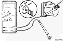
ActionMeasure the voltage from the fuel shutoff valve post to engine block ground. |
|
|
|
Fuel shutoff valve voltage greater than 11-VDC? |
||
| YES | NO | |
| No Repair | No Repair | |
| Guided Step 3B-1 – Check ECM keyswitch voltage. | ||
|---|---|---|
Conditions
ActionMeasure the voltage from the keyswitch input SIGNAL wire of the OEM harness to engine block ground. |
|
|
|
Keyswitch voltage equal to battery voltage? |
||
| YES | NO | |
| No Repair |
Repair or replace the OEM power harness, or keyswitch, or check the battery connections. Use the following procedure found in the ISX CM871 and ISM CM876 Electronic Control System, Bulletin 4021560. Refer to Procedure 019-064 in Section 19. |
|
|
Repair complete
|
||
| Guided Step 3B-2 – Check the fuel shutoff valve wire. | ||
|---|---|---|
Conditions
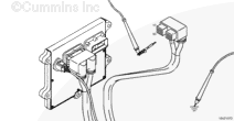
ActionMeasure the resistance from the fuel shutoff valve SIGNAL pin in the ECM connector to the fuel shutoff valve eyelet. Use the following procedure for general resistance measurement techniques. Use the following procedure found in the ISX CM871 and ISM CM876 Electronic Control System, Bulletin 4021560. Refer to Procedure 019-360 in Section 19. |
|
|
|
Less than 10 ohms? |
||
| YES | NO | |
|
Call for authorization to replace the ECM. Upon receipt of authorization, replace the ECM. Use the following procedure found in the ISX CM871 and ISM CM876 Electronic Control System, Bulletin 4021560. Refer to Procedure 019-031 in Section 19. |
Repair or replace the engine harness. Use the following procedure found in the ISX CM871 and ISM CM876 Electronic Control System, Bulletin 4021560. Refer to Procedure 019-043 in Section 19. |
|
|
Repair complete
|
||
| Guided Step 3B-3 – Check the ECM power and ground. | ||
|---|---|---|
Conditions
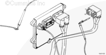
ActionMeasure the voltage from the ECM battery SUPPLY (-) to the ECM battery SUPPLY (+) pins in the ECM power harness connector. |
|
|
|
ECM battery supply voltage equal to the battery voltage? |
||
| YES | NO | |
|
Call for authorization to replace the ECM. Upon receipt of authorization, replace the ECM. Use the following procedure found in the ISX CM871 and ISM CM876 Electronic Control System, Bulletin 4021560. Refer to Procedure 019-031 in Section 19. |
No Repair | |
|
Repair complete
|
Repair complete
|
|
| Guided Step 3C – Check fuel shutoff valve resistance. | ||
|---|---|---|
Conditions
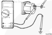
ActionMeasure the resistance from the fuel shutoff solenoid post to engine block ground. The fuel shutoff solenoid must be between 20°C [68°F] and 25°C [78°F] before using the resistance specifications listed. Use the following procedure for general resistance measurement techniques. Use the following procedure found in the ISX CM871 and ISM CM876 Electronic Control System, Bulletin 4021560. Refer to Procedure 019-360 in Section 19. |
|
|
|
Fuel shutoff solenoid resistance:
|
||
| YES | NO | |
| No Repair |
Replace the fuel shutoff solenoid. Use the following procedure found in the ISX CM871 and ISM CM876 Electronic Control System, Bulletin 4021560. Refer to Procedure 019-050 in Section 19. |
|
|
Repair complete
|
||
| Guided Step 3D – Check fuel shutoff valve actuator. | ||
|---|---|---|
Conditions
ActionCheck the valve disc, valve seat, and actuator disc for dirt, metal debris, bonding separation, corrosion, cracks, or wear. |
|
|
|
Debris or damage found on the valve disc, valve seat, or actuator disc? |
||
| YES | NO | |
|
Replace the damaged fuel shutoff valve component. Use the following procedure found in the ISX CM871 and ISM CM876 Electronic Control System, Bulletin 4021560. Refer to Procedure 019-050 in Section 19. |
No Repair | |
|
Repair complete
|
||
| Guided Step 3E – Check for correct priming pump operation, if equipped. | |
|---|---|
Conditions
ActionListen for lift pump operation after the keyswitch is turned to the ON position. Not all ISX engines use a priming pump and not all priming pumps actuate at keyswitch ON. Verify the type of pump system on the engine before beginning this step. |
|
|
Lift pump operates after turning the keyswitch ON or does the engine not use a priming pump? |
|
| YES | NO |
| No Repair |
Check or replace lift pump. Use the following procedure in the Signature™, ISX, and QSX15 Service Manual, Bulletin 3666239. Refer to Procedure 005-045 in Section 5. |
|
Repair complete
|
|
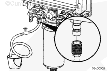
| Guided Step 3E-1 – Check priming pump pressure. | |
|---|---|
Conditions
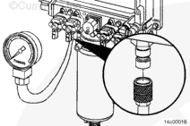
ActionMeasure the priming pressure at the quick connect fitting located on the top of the integrated fuel system module (IFSM). Use the following procedure in the Signature™, ISX, and QSX15 Service Manual, Bulletin 3666239. Refer to Procedure 005-045 in Section 5. |
|
|
Pump pressure meets the 69 kPa [10 psi] specification? |
|
| YES | NO |
| No Repair | No Repair |
|
Replace the lift pump. Use the following procedure in the Signature™, ISX, and QSX15 Service Manual, Bulletin 3666239. Refer to Procedure 005-045 in Section 5.
|
|
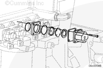
| Guided Step 3F – Check for coolant in the EGR transfer tube. | |
|---|---|
Conditions
ActionRemove the EGR transfer hose from the EGR cooler outlet. |
|
|
Coolant present in the crossover tube? |
|
| YES | NO |
|
See the Coolant Loss – Internal symptom tree. |
Perform the next troubleshooting procedure as outlined in Step 2 |
|
Repair complete
|
|
Guided Step 4 – Fuel system checks.
| Guided Step 4A – Verify the fuel system has been primed. | |
|---|---|
Conditions
ActionVerify the fuel system has been primed. If entering this tree after a component has been replaced in the fuel system, or after the engine has been emptied of fuel, verify the fuel system has been properly primed before proceeding.
|
|
|
Fuel system been properly primed? |
|
| YES | NO |
| No Repair |
Prime the fuel system.
|
|
Repair complete
|
|
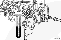
| Guided Step 4B – Check for air in the fuel. | ||
|---|---|---|
Conditions
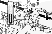
ActionConnect the equipment to the quick-connect fitting at the fuel module as shown.
|
|
|
|
Air bubbles visible in the coil of clear tubing? |
||
| YES | NO | |
|
Locate and correct the cause of air ingestion in the OEM fuel supply system or damaged fuel filter sealing ring. With EGR Check the ECM cooling plate, associated plumbing, and o-ring seals for failures that can cause air ingestion. Repair or replace the malfunctioning component.
|
No Repair | |
|
Repair complete
|
||
| Guided Step 4C – Check fuel inlet restriction. | ||
|---|---|---|
Conditions
ActionIf the engine uses a priming pump, wait until after the priming pump has turned off and observe the reading on the vacuum gauge. Check the fuel inlet restriction. Use the following procedure in the Signature™, ISX, and QSX15 Service Manual, Bulletin 3666239. Refer to Procedure 006-020 in Section 6. |
|
|
|
Fuel inlet restriction less than the specifications listed below? Dirty – 305 mm-Hg [12 in-Hg]; – New – 203 mm-Hg [8 in-Hg] |
||
| YES | NO | |
| No Repair |
Locate the cause of high fuel inlet restriction. Check the suction-side fuel filter, fuel supply lines, and inlet check valve. |
|
|
Repair complete
|
||
| Guided Step 4D – Check drain line restriction. | ||
|---|---|---|
Conditions
ActionObserve reading on the pressure gauge. |
|
|
|
Fuel drain line restriction less than 229 mm-Hg [9 in-Hg]? |
||
| YES | NO | |
| No Repair |
Locate the cause of high fuel drain line restriction in the OEM fuel return line. |
|
|
Repair complete
|
||
| Guided Step 4E – Check rail fuel pressure. | ||
|---|---|---|
Conditions
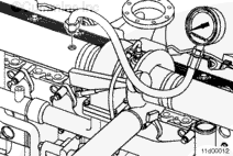
ActionRead the rail fuel pressure at low idle and high idle. Read the rail fuel pressure while cranking if the engine will not start.
|
|
|
|
Rail fuel pressure meet the specification? |
||
| YES | NO | |
| No Repair | No Repair | |
|
Perform the next troubleshooting procedure as outlined in Step 2
|
with EGR 4E-2
|
|
| Guided Step 4E-1 – Check the pressure side fuel filter restriction. | ||
|---|---|---|
Conditions
ActionRead the fuel pressure drop across the pressure side fuel filter at high idle or while cranking if the engine will not start. |
|
|
|
Pressure-side fuel filter pressure drop less than 517 kPa [75 psi]? |
||
| YES | NO | |
| No Repair |
Replace the pressure side fuel filter. Use the following procedure in the Signature™, ISX, and QSX15 Service Manual, Bulletin 3666239. Refer to Procedure 006-015 in Section 6. |
|
|
Repair complete
|
||
| Guided Step 4E-2 – Check 1724 kPa [250 psi] pressure regulator. | ||
|---|---|---|
Conditions
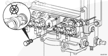
ActionRemove the 1724 kPa [250 psi] fuel pressure regulator.
|
|
|
|
1724 kPa [250 psi] pressure regulator free of debris or damage? |
||
| YES | NO | |
| No Repair |
Replace 1724 kPa [250 psi] regulator. Use the following procedure in the Signature™, ISX, and QSX15 Service Manual, Bulletin 3666239. Refer to Procedure 005-073 in Section 5. |
|
|
Repair complete
|
||
| Guided Step 4E-3 – Check 2206 kPa [320 psi] or 2620 kPa [380 psi] pressure regulator. | ||
|---|---|---|
Conditions
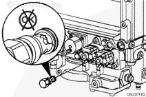
ActionRemove the 2206 kPa [320 psi] fuel pressure regulator.
|
|
|
|
Pressure regulator free of debris or damage? |
||
| YES | NO | |
|
Replace the gear pump module. Use the following procedure in the Signature™, ISX, and QSX15 Service Manual, Bulletin 3666239. Refer to Procedure 005-016 in Section 5. |
Replace 2620 kPa [380 psi] regulator. Use the following procedure in the Signature™, ISX, and QSX15 Service Manual, Bulletin 3666239. Refer to Procedure 005-073 in Section 5. |
|
|
Repair complete
|
Repair complete
|
|
Guided Step 5 – Injector and Actuator Diagnostics.
| Guided Step 5A – Perform the injector check valve leak test. | |
|---|---|
ActionPerform the injector check valve leak test to check for internal injector check valve damage. Use the following procedure in the Signature™, ISX, and QSX15 Service Manual, Bulletin 3666239. Refer to Procedure 006-026 in Section 6. |
|
|
Injector leak test detects a leaking injector? |
|
| YES | NO |
|
Replace the leaking injector. Use the following procedure in the Signature™, ISX, and QSX15 Service Manual, Bulletin 3666239. Refer to Procedure 006-026 in Section 6. |
No Repair |
|
Repair complete
|
|
| Guided Step 5B – Perform INSITE™ electronic service tool Cylinder Performance Test. | |
|---|---|
Conditions
ActionPerform the INSITE™ electronic service tool Cylinder Performance Test. During the initial 30 seconds of the Cylinder Performance Test, INSITE™ electronic service tool is checking to make sure all parameters have been met to enter the test. Once the initial Pass or Fail reading is displayed, the test is live for the next 2 minutes. Monitor the display to see if cylinders or banks drop out during this 2 minute window. A cylinder can switch from pass to fail and back to pass quickly, so monitor the screen closely. |
|
|
INSITE™ electronic service tool Cylinder Performance Test identifies a single malfunctioning injector? |
|
| YES | NO |
| No Repair | No Repair |
| Guided Step 5B-1 – Perform INSITE™ electronic service tool Cylinder Performance Test at 600 rpm. | |
|---|---|
Conditions
ActionSkip this step and move on to step 5B-2 if the rpm value is the same as that used in step 5B. Adjust the low speed to 600 rpm and perform INSITE™ electronic service tool Cylinder Performance Test. During the initial 30 seconds of the Cylinder Performance Test, INSITE™ electronic service tool is checking to make sure all parameters have been met to enter the test. Once the initial Pass or Fail reading is displayed, the test is live for the next 2 minutes. Monitor the display to see if cylinders or banks drop out during this 2 minute window. A cylinder can switch from pass to fail and back to pass quickly, so monitor the screen closely. |
|
|
INSITE™ electronic service tool Cylinder Performance Test identifies a single malfunctioning injector? |
|
| YES | NO |
| No Repair | No Repair |
| Guided Step 5B-2 – Perform INSITE™ electronic service tool Cylinder Performance Test at 700 rpm. | |
|---|---|
Conditions
The idle speed may need to be adjusted to perform this test. Toggle the cruise control increment/decrement switch to see if the idle speed can be adjusted. If not, use INSITE™ electronic service tool to either enable the Adjustable Low Idle Speed feature or adjust the Low Idle Speed. ActionSkip this step and move on to step 5B-3 if the RPM value is the same as that used in step 5B. Adjust the low speed to 700 rpm and perform INSITE™ electronic service tool Cylinder Performance Test. During the initial 30 seconds of the Cylinder Performance Test, INSITE™ electronic service tool is checking to make sure all parameters have been met to enter the test. Once the initial Pass or Fail reading is displayed, the test is live for the next 2 minutes. Monitor the display to see if cylinders or banks drop out during this 2 minute window. A cylinder can switch from pass to fail and back to pass quickly, so monitor the screen closely. |
|
|
INSITE™ electronic service tool Cylinder Performance Test identifies a single malfunctioning injector? |
|
| YES | NO |
| No Repair | No Repair |
| Guided Step 5B-3 – Perform INSITE™ electronic service tool Cylinder Performance Test at 800 rpm. | |
|---|---|
Conditions
The idle speed may need to be adjusted to perform this test. Toggle the cruise control increment/decrement switch to see if the idle speed can be adjusted. If not, use INSITE™ electronic service tool to either enable the “Adjustable Low Idle Speed” feature or adjust the Low Idle Speed. ActionSkip this step and move on to step 5C if the rpm value is the same as that used in step 5B. Adjust the low speed to 800 rpm and perform INSITE™ electronic service tool Cylinder Performance Test. During the initial 30 seconds of the Cylinder Performance Test, INSITE™ electronic service tool is checking to make sure all parameters have been met to enter the test. Once the initial Pass or Fail reading is displayed, the test is live for the next 2 minutes. Monitor the display to see if cylinders or banks drop out during this 2 minute window. A cylinder can switch from pass to fail and back to pass quickly, so monitor the screen closely. |
|
|
INSITE™ electronic service tool Cylinder Performance Test identifies a single malfunctioning injector? |
|
| YES | NO |
| No Repair | No Repair |
| Guided Step 5C – Perform INSITE™ electronic service tool Cylinder Cutout Test | |
|---|---|
Conditions
ActionPerform INSITE™ electronic service tool cylinder cutout test. A failing cylinder will have no effect on engine sound and operation when cut out using this test. |
|
|
All cylinders pass the cylinder cutout test? |
|
| YES | NO |
| No Repair | No Repair |
| Guided Step 5C-1 – Perform INSITE™ electronic service tool cylinder cutout test on individual injector banks. | |
|---|---|
Conditions
ActionPerform INSITE™ electronic service tool cylinder cutout test.
|
|
|
Malfunctioning bank of injectors isolated by operating the engine on either bank of injectors? |
|
| YES | NO |
| No Repair | No Repair |
| Guided Step 5C-2 – Perform INSITE™ electronic service tool Cylinder Cutout Test single cylinder operation. | |
|---|---|
Conditions
ActionPerform INSITE™ electronic service tool cylinder cut out test. Operate the engine on the cylinder identified by the Cylinder Performance Test by disabling five cylinders with INSITE™ electronic service tool and only operating on the suspect cylinder. To disable five cylinders with INSITE™ electronic service tool, click on the cylinder numbers until only one cylinder is enabled. The engine should roughly maintain idle speed when operating on a single cylinder. A weak or misfiring cylinder will be detected if the engine dies or can not maintain idle speed when operating on a single cylinder. Continue testing all six cylinders by operating the engine on each individual injector. If the engine will not run on one cylinder regardless of the cylinder selected, increase the idle RPM and retest. Do not run the engine on one cylinder for an extended period of time. |
|
|
Malfunctioning injector isolated by operating the engine on a single injector? |
|
| YES | NO |
| No Repair | No Repair |
| Guided Step 5C-3 – Verify overhead adjustments are correct for the suspected malfunctioning injector. | |
|---|---|
Conditions
ActionMeasure the overhead settings for the suspected malfunctioning injector.
|
|
|
Overhead settings within the reset limits outlined in Procedure 003-004? |
|
| YES | NO |
|
Replace the malfunctioning injector. Use the following procedure in the Signature™, ISX, and QSX15 Service Manual, Bulletin 3666239. Refer to Procedure 006-026 in Section 6. |
Adjust the overhead settings. Use the following procedure in the Signature™, ISX, and QSX15 Service Manual, Bulletin 3666239. Refer to Procedure 003-004 in Section 3. Perform the Cylinder Performance Test to determine if a misfire still exists after adjusting the overhead settings. |
|
Repair complete
|
|
| Guided Step 5D – Swap the front and rear metering actuators. | |
|---|---|
Conditions
ActionSwap the front and rear metering actuators to determine if the malfunctioning bank of cylinders follows a specific metering actuator.
|
|
|
Cylinder performance test finds a malfunctioning bank? |
|
| YES | NO |
|
Replace the malfunctioning metering actuator.
|
No Repair |
|
Repair complete
|
|
| Guided Step 5E – Swap the front and rear timing actuators | |
|---|---|
Conditions
ActionSwap the front and rear timing actuators to determine if the malfunctioning bank of cylinders follows a specific timing actuator.
|
|
|
Malfunctioning bank follows the timing actuator? |
|
| YES | NO |
|
Replace the timing actuator. Use the following procedure found in the ISX CM871 and ISM CM876 Electronic Control System, Bulletin 4021560. Refer to Procedure 019-111 in Section 19. |
No Repair |
|
Repair complete
|
|
| Guided Step 5F – Monitor the engine percent load value with INSITE™ electronic service tool. (Perform this step for troubleshooting low power only.) | |
|---|---|
Conditions
ActionMonitor the engine percent load value with INSITE™ electronic service tool with the engine running at idle. |
|
|
Engine percent load value consistently above 8 percent? |
|
| YES | NO |
|
Replace both metering actuators. Use the following procedure in the CM871 and CM876 Electronic Control Systems, ISX and ISM Engines Troubleshooting and Repair Manual, Bulletin 4021560. Refer to Procedure 019-110 in Section 19. |
No Repair |
|
Repair complete
|
Perform the next troubleshooting procedure as outlined in Step 2
|
Guided Step 6 – Air handling diagnostic checks.
| Guided Step 6A – Start the engine and read the fault codes. | |
|---|---|
Conditions
ActionCheck the fault codes with the engine running.
|
|
|
Active fault codes? |
|
| YES | NO |
| No Repair | No Repair |
|
Go to appropriate fault code troubleshooting tree
|
|
| Guided Step 6B – Check air intake restriction. | ||
|---|---|---|
Conditions
ActionCheck the intake system restriction by installing a vacuum gauge or water manometer into the air intake system. Use the following procedure in the Signature™, ISX, and QSX15 Service Manual, Bulletin 3666239. Refer to Procedure 010-031 in Section 10. |
|
|
|
Air intake restriction greater than 635 mm-H2O [25 in-H2O] for a used air filter or 254 mm-H2O [10 in-H2O] for a new filter? |
||
| YES | NO | |
|
Correct the cause of high intake air restriction. Check for a plugged air filter or restricted air intake piping. |
No Repair | |
|
Repair complete
|
||
| Guided Step 6C – Inspect the charge-air cooler | ||
|---|---|---|
Conditions
ActionPressure test the charge-air cooler.
|
|
|
|
Pressure drop 34 kPa [5 psi] or less in 15 seconds? |
||
| YES | NO | |
| No Repair |
Repair the charge-air cooler assembly. Refer to the OEM service manual. |
|
|
Repair complete
|
||
| Guided Step 6D – Inspect the turbocharger blades for damage. | |
|---|---|
Conditions
ActionInspect the compressor and turbine fins for damage or wear. Use the following procedure in the Signature™, ISX, and QSX15 Service Manual, Bulletin 3666239. Refer to Procedure 010-033 in Section 10. |
|
|
Damage found on turbocharger blades? |
|
| YES | NO |
|
Replace the turbocharger. Use the following procedure in the Signature™, ISX, and QSX15 Service Manual, Bulletin 3666239. Refer to Procedure 010-033 in Section 10. |
No Repair |
|
Repair complete
|
|
| Guided Step 6E – Inspect the turbocharger shaft movement. | |
|---|---|
Conditions
ActionInspect the sector gear on the turbocharger for damaged or broken gear teeth. Move the sector gear lever on the turbocharger bearing housing up and down from stop to stop. Check for smooth movement between the stops. There will be an initial friction force that must be overcome before the actuator lever will move. Once movement is started, the actuator lever should move to the other stop position by hand. Use the following procedure in the Signature™, ISX and QSX15 Service Manual, Bulletin 3666239. Refer to Procedure 010-134 in Section 10. |
|
|
Nozzle slides evenly from stop to stop and gear teeth undamaged? |
|
| YES | NO |
|
Install the turbocharger actuator. Use the following procedure in the Signature™, ISX and QSX15 Service Manual, Bulletin 3666239. Refer to Procedure 010-134 in Section 10. |
A turbocharger mechanical malfunction has been detected. This malfunction may have been caused by debris exiting the engine, causing the turbocharger nozzle to stop moving. Inspect the base engine components for damage. Inspect the turbocharger for repair and reuse, if possible. Use the following procedure in the Signature™, ISX and QSX15 Service Manual, Bulletin 3666239. Refer to Procedure 010-145 in Section 10. |
|
Perform new troubleshooting procedure as outlined in Step 2.
|
Repair complete
|
Guided Step 7 – Check EGR valve for proper operation.
| Guided Step 7A – Check for EGR-related fault codes | |
|---|---|
Conditions
ActionCheck for any EGR-related fault codes. |
|
|
EGR-related fault codes present? |
|
| YES | NO |
|
Troubleshoot electronic fault codes. |
No Repair |
|
Appropriate fault code troubleshooting trees
|
|
| Guided Step 7B – Check for inactive EGR differential pressure sensor fault codes. | |
|---|---|
Conditions
ActionCheck for active fault codes.
|
|
|
Fault Code 1866, 2273, or 2274 active? |
|
| YES | NO |
| No Repair | No Repair |
|
Appropriate fault code troubleshooting tree
|
|
| Guided Step 7C – Check the EGR differential pressure tubes for leaks. | |
|---|---|
Conditions
ActionCheck the lines for leaks. |
|
|
Leaks detected at either the low or high EGR differential pressure tubes? |
|
| YES | NO |
|
Tighten the fittings or replace the EGR differential pressure tube. Use the following procedure in the Signature™, ISX, and QSX15 Service Manual, Bulletin 3666239. Refer to Procedure 011-026 in Section 11. |
No Repair |
|
Repair complete
|
|
| Guided Step 7D – Check the EGR differential pressure sensor adapter for leaks. | |
|---|---|
Conditions
ActionInspect the EGR differential pressure sensor adapter for leaks.
|
|
|
Leaks detected at the EGR differential pressure sensor adapter? |
|
| YES | NO |
|
Replace the EGR differential pressure sensor adapter. Use the following procedure in the Signature™, ISX, and QSX15 Service Manual, Bulletin 3666239. Refer to Procedure 011-028 in Section 11. |
No Repair |
|
Repair complete
|
|
| Guided Step 7E – Check the EGR differential pressure tubes for plugging. | |
|---|---|
Conditions
ActionInspect the EGR differential pressure tubes for restrictions, soot plugging, and plugging. |
|
|
Debris or soot found in either EGR differential pressure tube? |
|
| YES | NO |
|
Clear the debris or replace the EGR differential pressure tube.
Remove the exhaust aftertreatment system from the vehicle and inspect for reuse.
|
No Repair |
|
Repair complete
|
|
| Guided Step 7F – Check for air leaks in the EGR system. | |
|---|---|
ActionCheck for leaks in the EGR connection tubing and connections. Soot streaks are noticeable where leaks are present. |
|
|
Leaks found in the EGR connection tubing? |
|
| YES | NO |
|
Repair any leaks in the EGR system. |
No Repair |
|
Repair complete
|
Perform the next troubleshooting procedure as outlined in Step 2
|
Guided Step 8 – Verify electronic features operating correctly.
| Guided Step 8A – Verify accelerator pedal travel. | |
|---|---|
Conditions
ActionWith INSITE™ electronic service tool, monitor accelerator pedal while fully depressing and releasing the accelerator pedal. |
|
|
Accelerator pedal reads 0 percent when the accelerator is released and 100 percent when the accelerator is depressed? |
|
| YES | NO |
| No Repair |
Determine and correct the cause of accelerator pedal restriction. |
|
Repair complete
|
|
| Guided Step 8B – Monitor vehicle speed. | |
|---|---|
Conditions
ActionWith INSITE™ electronic service tool, monitor vehicle speed while the vehicle is not moving. |
|
|
Vehicle speed reads 0 when the vehicle is not moving? |
|
| YES | NO |
| No Repair |
Check the vehicle speed sensor and circuit or locate the cause of the vehicle speed interference. |
|
Repair complete
|
|
| Guided Step 8C – Verify electronic feature settings are correct. | |
|---|---|
Conditions
ActionWith INSITE™ electronic service tool, verify the following adjustable parameters are correctly set:
|
|
|
Electronic features set correctly? |
|
| YES | NO |
| No Repair |
Correct programmable features. |
|
Repair complete
|
|
| Guided Step 8D – Check the ambient air pressure sensor accuracy | |
|---|---|
Conditions
ActionCheck for correct barometric pressure sensor readings.
|
|
|
Barometric pressure sensor reading in INSITE™ electronic service tool within 5 percent of the present local barometric pressure reading? |
|
| YES | NO |
| No Repair |
Replace the barometric pressure sensor. Use the following procedure found in the ISX CM871 and ISM CM876 Electronic Control System, Bulletin 4021560. Refer to Procedure 019-004 in Section 19. |
|
Repair complete
|
|
| Guided Step 8E – Check the intake manifold pressure sensor accuracy. | |
|---|---|
Conditions
ActionConnect a mechanical intake manifold pressure gauge to the engine, as close to the intake manifold pressure sensor as possible.
|
|
|
INSITE™ electronic service tool reading within 17 kPa [2.5 psi] of mechanical gauge reading? |
|
| YES | NO |
| No Repair |
Remove and clean the intake manifold pressure sensor. Use the following procedure found in the ISX CM871 and ISM CM876 Electronic Control System, Bulletin 4021560. Refer to Procedure 019-159 in Section 19. |
|
Perform the next troubleshooting procedure as outlined in Step 2
|
Repair complete
|
Guided Step 9 – Perform base engine mechanical checks.
| Guided Step 9A – Verify injection timing is correct. | |
|---|---|
Conditions
ActionVerify injection timing is correct. Measure the injection timing. Use the following procedure in the Signature™, ISX, and QSX15 Service Manual, Bulletin 3666239. Refer to Procedure 006-025 in Section 6. If the injection timing is found to be out of specification, bart the engine to “insert pin” and install the crankshaft pin. Install the appropriate injector camshaft wedge to set the correct injection timing. Use the following procedure in the Signature™, ISX, and QSX15 Service Manual, Bulletin 3666239. Refer to Procedure 001-088 in Section 1. |
|
|
Injection timing correct? |
|
| YES | NO |
| No Repair |
Correct the injection timing. Use the following procedure in the Signature™, ISX, and QSX15 Service Manual, Bulletin 3666239. Refer to Procedure 001-088 in Section 1. |
|
Repair complete
|
|
| Guided Step 9B – Verify overhead adjustments are correct. | |
|---|---|
Conditions
ActionMeasure the overhead settings. Use the following procedure in the Signature™, ISX, and QSX15 Service Manual, Bulletin 3666239. Refer to Procedure 003-004 in Section 3. |
|
|
Overhead settings within the reset limits? |
|
| YES | NO |
| No Repair |
Adjust the overhead settings. Use the following procedure in the Signature™, ISX, and QSX15 Service Manual, Bulletin 3666239. Refer to Procedure 003-004 in Section 3. |
|
Repair complete
|
|
| Guided Step 9C – Verify engine brake adjustment. | |
|---|---|
Conditions
ActionVerify the engine brakes are operating correctly.
|
|
|
Engine brake settings within the reset limits? |
|
| YES | NO |
| No Repair |
Adjust the engine brake settings. Use the following procedure in the Signature™, ISX, and QSX15 Service Manual, Bulletin 3666239. Refer to Procedure 020-004 in Section 20. |
|
Repair complete
|
|
| Guided Step 9D – Verify crankshaft tone wheel is not loose. | |
|---|---|
Conditions
ActionOperate the engine with the crankshaft position sensor unplugged and identify if idle quality improves.
|
|
|
Crankshaft tone wheel loose? |
|
| YES | NO |
|
Repair the tone wheel. Use the following procedure in the Signature™, ISX, and QSX15 Service Manual, Bulletin 3666239. Refer to Procedure 001-069 in Section 1. |
No Repair |
|
Repair complete
|
|
| Guided Step 9E – Check exhaust restriction. | ||
|---|---|---|
Conditions
ActionCheck exhaust restriction by installing a pressure gauge into the exhaust system just past the turbocharger outlet. If a port is not found in the exhaust system, remove the exhaust gas temperature 1 sensor and install the pressure gauge in the temperature sensor port. Use the following procedure in the Signature™, ISX, and QSX15 Service Manual, Bulletin 3666239. Refer to Procedure 011-009 in Section 11. |
|
|
|
Exhaust restriction greater than 305 mm-Hg [12.0 in-Hg]? |
||
| YES | NO | |
|
Remove the exhaust aftertreatment system from the vehicle and inspect for reuse. Use the following procedure in the Signature™, ISX, and QSX15 Service Manual, Bulletin 3666239. Refer to Procedure 011-050 in Section 11. |
No Repair | |
|
Repair complete
|
||
;)
;)
;)
;)
;)
;)
;)
;)
;)
;)
;)
;)
;)
;)
;)
;)
;)
;)
;)
;)
;)
;)
;)
;)
;)
;)
;)
;)
;)
;)
| Guided Step 9F – Verify engine blowby is within specification. | |
|---|---|
Conditions
ActionLoad engine to rated rpm on a chassis dynamometer. Measure the engine blowby. Use the following procedure in the Signature™, ISX, and QSX15 Service Manual, Bulletin 3666239. Refer to Procedure 014-010 in Section 14. |
|
|
Engine blowby measurements within specification? |
|
| YES | NO |
| No Repair |
Engine may need to be rebuilt. See the engine specifications. |
|
Perform the next troubleshooting procedure as outlined in Step 2
|
Repair complete
|
Guided Step 10 – Aftertreatment checks.
| Guided Step 10A – Check for aftertreatment-related fault codes. | |
|---|---|
Conditions
ActionUse INSITE™ electronic service tool to read the fault codes. Check for any aftertreatment fault codes, specifically fault codes related to high soot in the aftertreatment particulate trap, face plugging of the aftertreatment catalyst, and aftertreatment catalyst efficiency. |
|
|
Fault codes related to the aftertreatment system found to be active? |
|
| YES | NO |
| No Repair | No Repair |
|
Appropriate fault code troubleshooting tree
|
|
| Guided Step 10B – Perform basic aftertreatment troubleshooting checks. | |
|---|---|
ActionThe following items must be checked or verified before continuing:
|
|
|
All parts inspected and appear to be functioning properly? |
|
| YES | NO |
| No Repair |
Correct the damage and verify the complaint is no longer present after repair. |
|
Repair complete
|
|
| Guided Step 10C – Check for signs of internal damage to the aftertreatment system. | |
|---|---|
Conditions
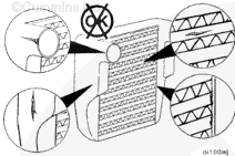
ActionQuickly snap the throttle pedal accelerating the engine from low idle to high idle while checking for smoke at the exhaust outlet. Inspect for the following during the snap throttle acceleration.
If the aftertreatment system is operating correctly, no visible smoke will be present during the snap throttle acceleration. Any visible smoke is an indication of a possible malfunction in the aftertreatment system. |
|
|
Visible smoke (black or white) present during the snap throttle acceleration? |
|
| YES | NO |
|
Damage in the aftertreatment system. Remove the exhaust gas aftertreatment system from the vehicle and inspect for reuse. Use the following procedure in the Signature™, ISX, and QSX15 Service Manual, Bulletin 3666239. Refer to Procedure 011-050 in Section 11. |
No Repair |
|
Repair complete. Troubleshoot the smoke complaint, use the proper TT tree steps
|
|
| Guided Step 10D – Check exhaust restriction. | ||
|---|---|---|
Conditions
ActionCheck exhaust restriction by installing a pressure gauge into the exhaust system just past the turbocharger outlet. If a port is not found in the exhaust system, remove the exhaust gas temperature 1 sensor and install the pressure gauge in the temperature sensor port. Use the following procedure in the Signature™, ISX, and QSX15 Service Manual, Bulletin 3666239. Refer to Procedure 011-009 in Section 11. |
|
|
|
Exhaust restriction greater than 305 mm-Hg [12.0 in-Hg]? |
||
| YES | NO | |
|
Remove the exhaust aftertreatment system from the vehicle and inspect for reuse. Use the following procedure in the Signature™, ISX, and QSX15 Service Manual, Bulletin 3666239. Refer to Procedure 011-049 in Section 11. |
No Repair | |
|
Repair complete
|
Perform the next troubleshooting procedure as outlined in Step 2
|
|