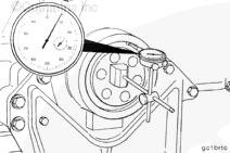
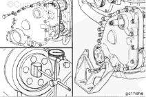
Mount a dial indicator on the front face of the crankshaft. Place the indicator plunger against the oil seal bore, and set the dial indicator at “0” (zero).
Rotate the crankshaft one complete revolution while monitoring the indicator. Use the accessory drive nut to bar the engine over. The total indicator reading
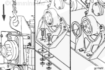
Lower the engine to the crossmember. Install and tighten the capscrews which hold the front engine support to the crossmember. Refer to the OEM service manual for torque specifications.
Hello, I'm Jack, a diesel engine fan and a blogger. I write about how to fix and improve diesel engines, from cars to trucks to generators. I also review the newest models and innovations in the diesel market. If you are interested in learning more about diesel engines, check out my blog and leave your feedback.
View all posts by Jack


;)
;)
;)
;)
;)
;)
;)
;)
;)
;)
;)
;)