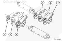
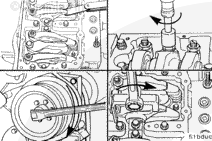
Install the exhaust (1), injector (2), and intake (3) rocker levers onto the shaft.
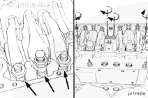
The two levers closest to the center of the rocker housing are the intake valve rocker levers. The levers closest to the end of the rocker housing are the exhaust valve rocker levers.
If the adjusting screws protrude beyond the maximum listed below, the push rods can be damaged when the rocker shaft capscrews are tightened. Do not attempt to install the rocker lever shaft assemblies without resetting the lash.
Loosen the rocker lever adjusting screws so there is a maximum of 32 mm [1.250 in] from the top surface of the lever and the ball end of the adjusting screw.
Hello, I'm Jack, a diesel engine fan and a blogger. I write about how to fix and improve diesel engines, from cars to trucks to generators. I also review the newest models and innovations in the diesel market. If you are interested in learning more about diesel engines, check out my blog and leave your feedback.
View all posts by Jack


 CAUTION
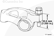


;)
;)
;)
;)
;)
;)
;)
;)
;)
;)
;)
;)