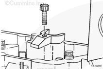
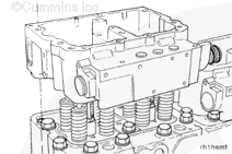
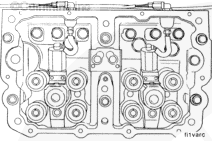
Remove the crossheads. Make sure to mark them appropriately so they can be installed in the same location and orientation during the installation procedure.
NOTE: Excessive crosshead wear can result if the crossheads are
not
installed in their original locations. The larger hole on the underside of the crosshead
must be oriented toward the exhaust side of the engine.
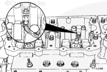
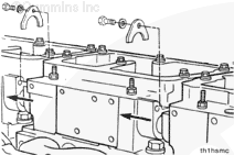
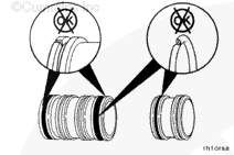
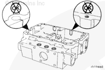
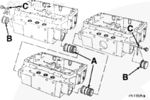
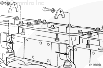
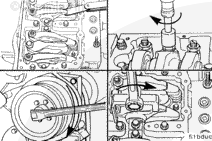
Remove the water manifold tube clamps. Use jumper tube removal tool, Part Number 3823819, to push or pry the adjacent water tubes into the rocker lever housing cavity.
For example, the tube between housing Number 1 and Number 2 must be pushed into housing Number 2. The tube between housing Number 2 and Number 3 must be pushed into housing Number 3.
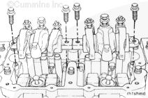
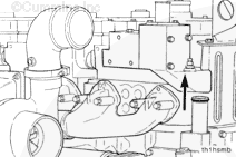
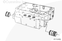
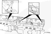
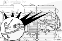
Install the water tubes (A) in the front of the Number 2 and Number 3 rocker lever housings. Install the plugs (B) in the front to the Number 1 rocker lever housing and in the rear of the Number 3 rocker lever housing.
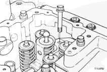
The injector must be fully seated before installing the hold down clamp. The hold down clamp can not pull the injector into the bore. Engine damage can occur if the injector is not fully seated.
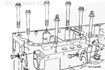
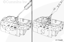
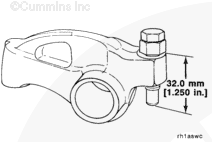
If the adjusting screws protrude beyond the maximum listed below, the push rods can be damaged when the housing capscrews are tightened. Do not attempt to install the rocker lever shaft assemblies again without resetting the lash.
Loosen the rocker lever adjusting screws so there is a maximum of 32.0 mm [1.25 in] from the top surface of the lever and the ball end of the adjusting screw.
Hello, I'm Jack, a diesel engine fan and a blogger. I write about how to fix and improve diesel engines, from cars to trucks to generators. I also review the newest models and innovations in the diesel market. If you are interested in learning more about diesel engines, check out my blog and leave your feedback.
View all posts by Jack

 WARNING

 CAUTION
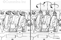


;)
;)
;)
;)
;)
;)
;)
;)
;)
;)
;)
;)
;)
;)
;)
;)
;)
;)
;)
;)
;)
;)
;)
;)
;)
;)
;)
;)
;)
;)
;)
;)
;)
;)
;)
;)
;)
;)
;)
;)
;)
;)
;)
;)
;)
;)
;)
;)
;)
;)
;)
;)
;)
;)
;)
;)