Flow Diagram
|
TOC |
|
|
|
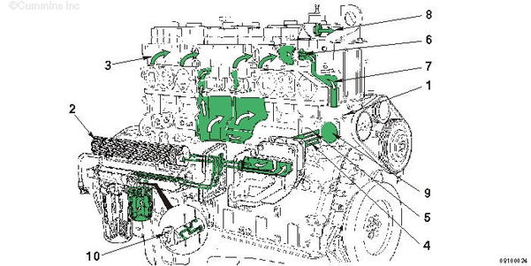
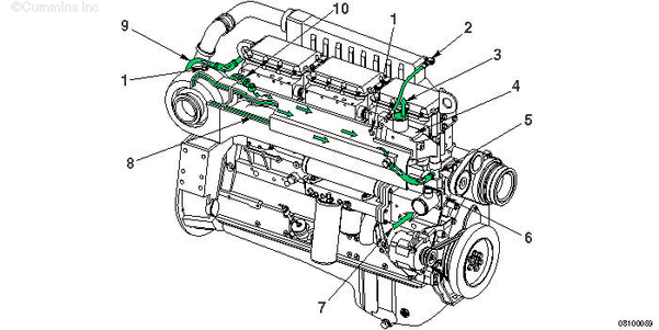
| Automotive Cooling System Flow Diagram |
- Water pump
- Oil cooler
- Water manifold
- Oil cooler supply
- Oil cooler return
- Thermostat
- Bypass
- To radiator
- Water pump inlet
- Coolant filter head shutoff valve.
|
|
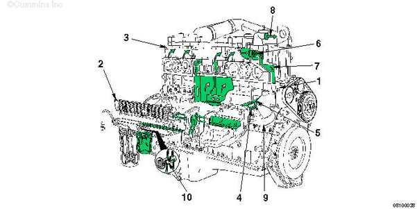
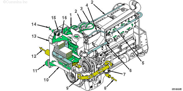
| Industrial Cooling System Flow Diagram |
- Water pump
- Oil cooler
- Water manifold
- Oil cooler supply
- Oil cooler return
- Thermostat
- Bypass
- To radiator
- Water pump inlet
- Coolant filter head shutoff valve.
|
|
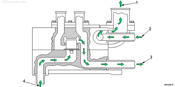
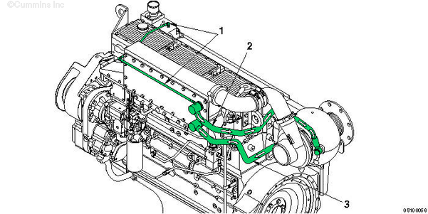
| CELECT™ Low Temperature Aftercooled (LTA) and Industrial Cooling System (LTA Thermostat Closed) |
- To Radiator
- From Aftercooler
- To Aftercooler
- From Water Pump.
|
|
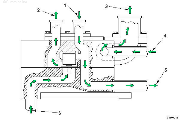
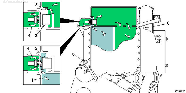
| CELECT™ Low Temperature Aftercooled (LTA) and Industrial Cooling System (LTA Thermostat Open) |
- From Aftercooler Radiator
- To Aftercooler Radiator
- To Radiator
- From Aftercooler
- To Aftercooler
- From Water Pump.
NOTE: The coolant plumbing has been modified to allow for the new shields.
|
|
| Marine Keeled Cooled and Heat Shields Cooling System Flows |
- Heat shield vent connections
- Coolant vent lines
- Coolant outlet to keel cooler
- Thermostat housing
- Keel cooler bypass return to coolant pump
- Coolant pump
- Coolant pump inlet from keel cooler
- Coolant cooled exhaust shield
- Aftercooler to turbocharger shield
- Turbocharger shield to exhaust manifold shield.
|
|
| Marine Heat Exchanger Seawater System Flows with Low Temperature Aftercooler |
- Coolant inlet to heat exchanger
- Heat shield vent lines
- Thermostat vent lines
- Aftercooler vent lines
- From aftercooler to turbocharger shield
- From low temperature aftercooler
- Sea water pump
- Sea water inlet
- Sea water inlet to heat exchanger
- Heat exchanger
- From heat exchanger to coolant pump
- Sea water outlet
- Expansion tank
- To low temperature thermostat
- From low temperature thermostat to low temperature aftercooler
- Low temperature aftercooler bypass.
|
|
| Marine Keeled Cooled Water Jacket Aftercooler |
- Aftercooler vent line
- From aftercooler to turbocharger shield
- From cylinder block to aftercooler.
|
|
| Marine Low Temperature Aftercooler Thermostat Flow |
- From low temperature aftercooler thermostat to low temperature aftercooler
- Low temperature aftercooler thermostat open
- Low temperature aftercooler thermostat closed
- To low temperature aftercooler thermostat
- Low temperature aftercooler bypass
- Sacrificial zinc plugs.
|
Last Modified: 28-Mar-2005
Published by Jack
Hello, I'm Jack, a diesel engine fan and a blogger. I write about how to fix and improve diesel engines, from cars to trucks to generators. I also review the newest models and innovations in the diesel market. If you are interested in learning more about diesel engines, check out my blog and leave your feedback.
View all posts by Jack

;)
;)
;)
;)
;)
;)
;)
;)
;)
;)
;)
;)
;)
;)
;)
;)