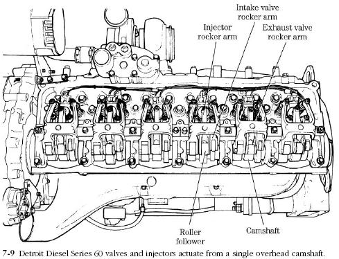
Two rocker arm configurations are used on OHV engines. Commercial and automotive engines developed from industrial engines generally pivot the rockers on single or double shafts, in Figs. 7-9 and 7-10. The earlier drawing is the most typical, because a single rocker drives each intake and exhaust valve. Figures 7-9 and 7-10 illustrate Detroit Diesel solutions to the problem of driving two valves from the same rocker arm. Regardless of the rocker configuration, the hollow pivot shaft doubles as an oil gallery, distributing oil to the rocker bushings through radially drilled ports. Rockers are steel forgings, case-hardened on the valve end and generally include provision for valve lash adjustment.
Shaft-type rockers are detached from the head as an assembly with the shaft while the pushrods are still engaged. Note the lay of the shaft and rockers, and if no identification marks are present, tag the forward end of the shaft as an assembly reference. Loosen the hold-down bolts slowly, a half-turn or so at a time following the factory-recommended breakout sequence. If no information is provided on this point, work from the center bolt outward. This procedure will distribute valve spring orces over the length of the shaft.

Set the rocker arm assembly aside and remove the pushrods, racking them in the order of removal with the cam-ends down. A length of four-by-four, drilled to accept the pushrods and with the front of the engine clearly marked, makes an inexpensive rack.
Although the task is formidable on a large engine, the rocker arms, together with spacers, locating springs, and wave washers, should be completely disassembled for cleaning and inspection. Critical areas are
• Adjusting screws—check the thread fit and screw tips. Screws are case-hardened: once the carburized “skin” is penetrated, it will be impossible to keep the valves adjusted.
• Rocker tips—with proper equipment, worn tips can usually be recontoured, quieting the engine.
• Rocker flanks—check for cracks radiating out from the fulcrum. Cracks tend to develop on the undersides of the rockers at the fillets.
• Bushings—wear concentrates on the engine side of the bushing and, when severe, is accompanied with severe scoring, which almost always involves the shaft. Clearance between the bushing and an unworn part of the shaft should be on the order of 0.002 in. Replacement bushings are generally available from the original equipment manufacture (OEM) or aftermarket. The old bushing is driven out with a suitable punch, and the replacement pressed into place and reamed to finish size. Aligning the bushing oil port with the rocker arm port is, of course, critical.
• Shaft—inspect the surface finish, mike bearing diameters, and carefully clean the shaft inner diameter (ID), clearing the oil ports with a drill bit. Do the same for the oil supply circuit. Rocker arms are remote from the pump, and lubrication is problematic.
Small engines in general and automotive plants derived from SI engines use pedestal-type rockers, of the type illustrated in Fig. 7-11. This technology, pioneered by Chevrolet in 1955, represents a considerable cost saving because the pivots compensate for dimensional inaccuracies and the rockers are steel stampings. Most examples lubricate through hollow pushrods. If rockers are removed, it is vital that they be assembled as originally found, together with fulcrum pieces and hold-down hardware.

The locknuts that secure the rockers to their studs should be renewed whenever the head is serviced. Other critical items are
• Studs—check for thread wear, nicks, distortion, and separation from the head. As far as I am aware, all diesel pedestal-type rocker studs thread into the cylinder head.
• Rocker pivots—the rocker pivots on a ball or a cylindrical bearing, secured by the stud nut, and known as the fulcrum seat (Fig. 7-12A). Reject the rocker, if either part is discolored, scored, or heat checked. How much wear is permissible on the rocker pivot is a judgment call.
• Fasteners—replace locknuts if nut threads show low resistance to turning, or for the considerable insurance value. Replace stud nuts if faces exhibit fractures (Fig. 7-12B).
• Rocker tips—look for evidence of impact damage that could point to a failed hydraulic lifter and possible valve tip, valve guide, or pushrod damage. For want of a better rule, replace the rocker when tip wear is severe enough to hang a fingernail.
