The compressor impeller is an aluminium alloy (LM- 16-WP or C-355T61) investment casting, with a gravity die-cast aluminium housing (LM-27-M). The design of the impeller is a compromise between aerodynamic requirements, mechanical strength and foundry capabilities. To achieve high efficiency, and minimum flow blockage, very thin and sharp impeller vanes are required, thickening at the root (impeller hub) for stress reasons. It is common practice to use splitter blades that start part way through the inducer, in order to maintain good flow guidance near the impeller tip without excessive flow blockage at the eye. Until recently the impeller vanes have been purely radial so that blades were not subjected to bending stress. However most recent designs incorporate backswept blades at the impeller tip since this has been shown to give better flow control and reduces flow distortion transmitted through from impeller to diffuser.
Automotive turbocharger compressor impeller, with splitter blades.
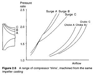
Typical design point pressure ratios fall in the range of 2 to 2.5:1, requiring impeller tip speeds of 300 to 350 m/s, hence small units of typically 0.08 m tip diameter rotate at 72 000 to 83 000 rev/min. In order to match wide differences in air flow requirements from one engine to another, a range of compressor impellers is available to fit the same turbocharger. These will be produced from one or two impeller castings, but with different tip widths and eye diameters generated by machining as shown in Figure 2.6, and matched with appropriate compressor housings. Usually up to ten or more alternative ‘trims’ are available but since the impeller tip diameter is unchanged and the hub diameter at the impeller eye is fixed by the shaft diameter, the flow passage variations alter the efficiency as well as flow characteristics of the impeller.
The compressor can be a loose or slight interference fit on the shaft, clamped by the compressor end nut. Impellers of most turbochargers are balanced before assembly onto the shaft, so that components can be interchanged without rebalancing.
Vaneless diffusers are used on all except very high pressure ratio compressors. Relative to the alternative vaned designs, the vaneless diffuser is slightly less efficient due to a longer gas flow path and poorer flow guidance, but has a substantially wider range of high operating efficiency. This is important in truck and passenger car applications where engine speed, and therefore mass flow range, is large. The volute acts not merely as a collector of air leaving the diffuser, but is usually designed to achieve a small amount of additional diffusion in its delivery duct. Generally the volute slightly overhangs the diffuser in order to reduce the overall diameter of the turbocharger. The volute and impeller casing are invariably formed as a single component.

