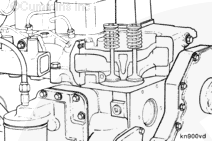
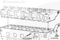
The cylinder head is a one-piece, cross-flow design with two valves per cylinder. The head has integrally cast valve guides and hardened valve seat surfaces that can be repaired in a machine shop using the appropriate service parts.
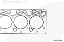
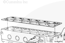
The cylinder head gasket is a specialized metal design with a printed o-seal on both sides around the water holes. An embossment in the gasket seals the cylinder bores. As discussed in the Cooling System, the gasket also provides orifices to control coolant flow.
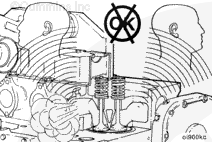
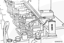
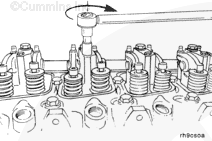
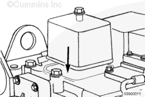
The sound emitted from the overhead can indicate a valve train problem. Loose rocker levers will clatter. A squeaking noise can mean lack of lubrication for the adjusting screw and the push rod socket.
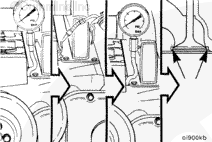
If the compression is low on one or more nonadjacent cylinders and the pressure can not be increased by oiling the rings, improper valve sealing is to be suspected.
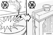
Fuel is flammable. Keep all cigarettes, flames, pilot lights, arcing equipment, and switches out of the work area and areas sharing ventilation to reduce the possibility of severe personal injury or death when working on the fuel system.
WARNING
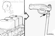
Batteries can emit explosive gases. To reduce the possibility of personal injury, always ventilate the compartment before servicing the batteries. To reduce the possibility of arcing, remove the negative (-) battery cable first and attach the negative (-) battery cable last.
WARNING
Coolant is toxic. Keep away from children and pets. If not reused, dispose of in accordance with local environmental regulations.
WARNING
Do not remove the pressure cap from a hot engine. Wait until the coolant temperature is below 50°C [120°F] before removing the pressure cap. Heated coolant spray or steam can cause personal injury.
Turn off the vehicle’s main fuel shutoff valve.
Disconnect the battery cables, negative (-) cable first.
When using solvents, acids, or alkaline materials for cleaning, follow the manufacturer’s recommendations for use. Wear goggles and protective clothing to reduce the possibility of personal injury.
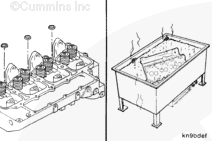
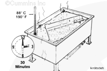
Clean the buildup of deposits from the coolant passages. Excessive deposits can be cleaned in an acid tank, but the expansion plugs must first be removed.
Do not mix gasoline, alcohol, or gasohol with diesel fuel. This mixture can cause an explosion.
WARNING
When using solvents, acids, or alkaline materials for cleaning, follow the manufacturer’s recommendations for use. Wear goggles and protective clothing to reduce the possibility of personal injury.
WARNING
Use skin and eye protection when handling caustic solutions to reduce the possibility of personal injury.
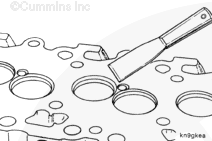
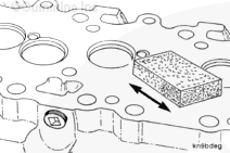
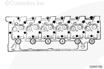
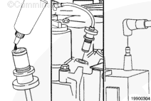
Clean the cylinder head combustion deck with a Scotch-Brite™ pad, or an equivalent cleaning pad, and diesel fuel or solvent.
Use skin and eye protection when handling caustic solutions to reduce the possibility of personal injury.
CAUTION
Do not use caustic or acidic solutions to clean the cylinder head capscrews. Use of these solutions can cause corrosion.
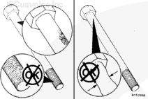
Use a petroleum-based solvent to clean the capscrews.
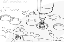
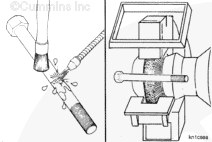
Clean the capscrew thoroughly with a wire brush or a soft wire wheel, or use a nonabrasive bead blast to remove deposits from the shank and the threads.
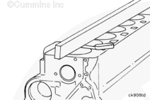
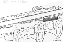
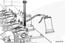
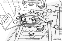
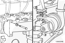
Use a straightedge and feeler gauge to measure the overall flatness of the cylinder block. The overall flatness, end-to-end and side-to-side, must not exceed 0.075 mm [0.003 in].
Inspect the combustion deck for any localized dips or imperfections. If present, the cylinder block head deck must be ground.
Refer to the Alternate Repair Manual, Bulletin 3666109, for grinding/milling procedures and limitations.
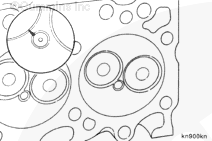
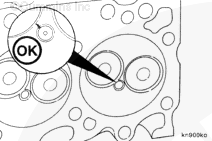
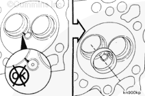
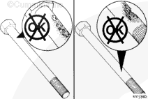
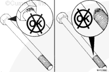
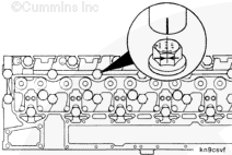
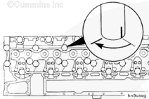
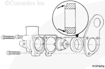
These guidelines apply only to cracks extending from the spark plug bore to the intake valve seats. Replace cylinder heads that exhibit valve bridge cracks in any other location.
If the crack extends into or through the valve seat, the cylinder head must be repaired by installing a valve seat insert according to the Alternative Repair Manual, Bulletin 3666109.
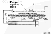
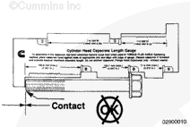
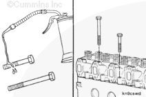
NOTE: If the capscrews are not damaged, they can be reused throughout the life of the engine unless the specified “free length” is exceeded.
Use capscrew length gauge, Part Number 3823921, or equivalent, to check the capscrew free length. Place the head of the capscrew in the appropriate slot with the flange against the base of the slot.
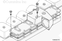
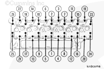
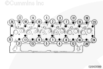
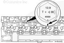
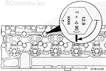
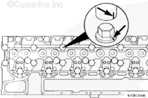
Retighten the short capscrews (numbers 1, 2, 3, 6, 7, 8, 9, 10, 11, 14, 15, 16, 17, 18, 19, 22, 23, 24, 25, and 26) because of cylinder head relaxation and to obtain proper cylinder head torque requirements.
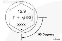
To turn the capscrew to the desired angle accurately, align the capscrew with the small “dot” and “window” that are marked on the capscrew head or use recommended torque angle gauge, Part Number 3823878, or equivalent, torque angle gauge for 19 mm [3/4-in] drive.
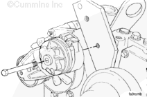
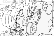
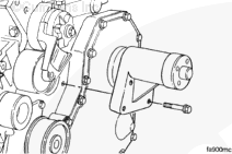
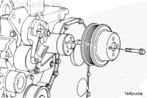
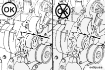
Check the alternator pulley alignment. Use a straightedge to make sure it is aligned with the other pulleys and is parallel to the front face of the block.
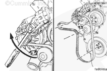
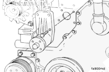
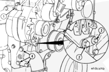
Service Tip: If difficulty is experienced installing the drive belt (the belt seems too short), position the belt over the grooved pulleys first; and then, while holding the tensioner up, slide the belt over the water pump pulley.
Coolant is toxic. Keep away from children and pets. If not reused, dispose of in accordance with local environmental regulations.
WARNING
Do not remove the pressure cap from a hot engine. Wait until the coolant temperature is below 50° [120°] before removing the pressure cap. Heated coolant spray or steam can cause personal injury.
WARNING
Batteries can emit explosive gases. To reduce the possibility of personal injury, always ventilate the compartment before servicing the batteries. To reduce the possibility of arcing, remove the negative (-) battery cable first and attach the negative (-) battery cable last.
WARNING
Fuel is flammable. Keep all cigarettes, flames, pilot lights, arcing equipment, and switches out of the work area and areas sharing ventilation to reduce the possibility of severe personal injury or death when working on the fuel system.
Hello, I'm Jack, a diesel engine fan and a blogger. I write about how to fix and improve diesel engines, from cars to trucks to generators. I also review the newest models and innovations in the diesel market. If you are interested in learning more about diesel engines, check out my blog and leave your feedback.
View all posts by Jack
 WARNING

 CAUTION
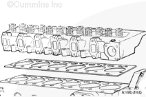


;)
;)
;)
;)
;)
;)
;)
;)
;)
;)
;)
;)
;)
;)
;)
;)
;)
;)
;)
;)
;)
;)
;)
;)
;)
;)
;)
;)
;)
;)
;)
;)
;)
;)
;)
;)
;)
;)
;)
;)
;)
;)
;)
;)
;)
;)
;)
;)
;)
;)
;)
;)
;)
;)
;)
;)
;)
;)
;)
;)
;)
;)
;)
;)
;)
;)
;)
;)
;)
;)
;)
;)
;)
;)
;)
;)
;)
;)
;)
;)
;)
;)
;)
;)
;)
;)
;)
;)
;)
;)
;)
;)
;)
;)
;)
;)
;)
;)
;)
;)
;)
;)
;)
;)
;)
;)
;)
;)
;)
;)
;)
;)
;)
;)
;)
;)
;)
;)
;)
;)
;)
;)
;)
;)
;)
;)
;)
;)
;)
;)
;)
;)
;)
;)