Do not remove the pressure cap from a hot engine. Wait until the coolant temperature is below 50° C [120°F] before removing the pressure cap. Heated coolant spray or steam can cause personal injury.
WARNING
Coolant is toxic. Keep away from children and pets. If not reused, dispose of in accordance with local environmental regulations.
WARNING
This component or assembly weighs greater than 23 kg [50 lb]. To prevent serious personal injury, be sure to have assistance or use appropriate lifting equipment to lift this component or assembly.
WARNING
To reduce the possibility of personal injury, avoid direct contact of hot oil with your skin.
WARNING
Some state and federal agencies have determined that used engine oil can be carcinogenic and cause reproductive toxicity. Avoid inhalation of vapors, ingestion and prolonged contact with used engine oil. If not reused, dispose of in accordance with local environmental regulations.
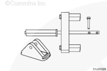
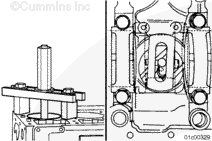
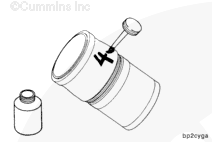
The cylinder puller must be installed and used as described to reduce the possibility of damage to the cylinder block. The puller plate must be parallel to the main bearing saddles and must not overlap the cylinder liner outside diameter.
Insert the cylinder liner puller onto the top of the cylinder block.
Do not use emery cloth or sandpaper to remove carbon from the cylinder liners. Aluminum oxide or silicon particles from emery cloth or sand paper can cause serious engine damage. Do not use any abrasives in the ring travel area. The cylinder liner can be damaged.
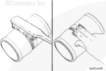
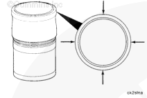
Use a soft wire brush to clean the flange seating area.
Use a fine fibrous, abrasive pad such as Scotch-Brite™ 7448, Part Number 3823258, or equivalent, to remove the remaining scale and rust.
When using solvents, acids, or alkaline materials for cleaning, follow the manufacturer’s recommendations for use. Wear goggles and protective clothing to reduce the possibility of personal injury.
WARNING
Wear safety glasses or a face shield, as well as protective clothing, to reduce the possibility of personal injury when using a steam cleaner or high pressure water.
WARNING
Wear appropriate eye and face protection when using compressed air. Flying debris and dirt can cause personal injury.
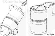
Use solvent or steam clean the cylinder liners and dry with compressed air.
Use clean 15W-40 oil to lubricate the inside circumference of the cylinder liners.
Allow oil to soak into the cylinder liner for 5 to 10 minutes.
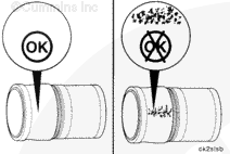
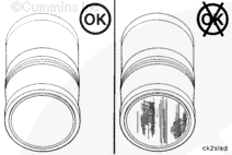
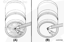
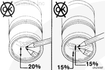
Replace the cylinder liner if a heavy polish is present over 20 percent of the piston ring travel area or 30 percent of the piston ring travel has both moderate and heavy polish and one half (15 percent) is heavy polish.
Cylinder liners of different design can not be mixed within an engine. All six cylinder liners must be of the same design.
There are two different designs of cylinder liners used. The design used in a particular engine is dependent on the engine’s production vintage.
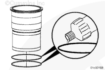
Engines assembled prior to engine serial number 14022615 have groove-top cylinder liners. They are characterized by a groove machined into the top surface of the cylinder liner flange.
Engines with serial number 14022615, and after, are assembled with flat-top cylinder liners. They are characterized by a cylinder liner flange that is flat, except for the fire dam.
Cylinder liners of different design can not be mixed within an engine. All six cylinder liners must be of the same design.
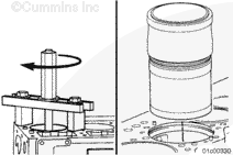
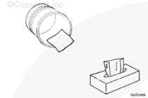
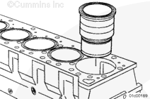
Install the cylinder liner into the cylinder block.
When acceptable and used cylinder liners are installed, rotate the cylinder liner 90 degrees from its original position in the engine. The thrust and anti-thrust surfaces must face the front and back of the cylinder block.
Use cylinder liner installation kit, Part Number 3162461, to seat the liner.
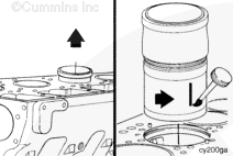
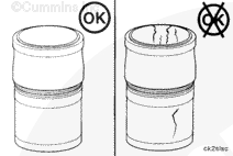
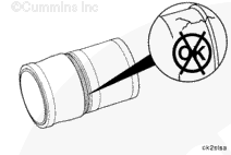
If the cylinder liner does not seat properly, remove it and inspect the cylinder liner bore seat and cylinder liner for nicks, burrs, or dirt.
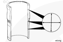
Because of design differences, the cylinder liner’s position (relative to the cylinder top deck) will be different.
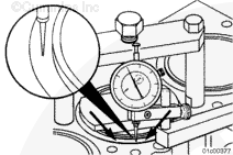
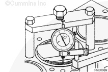
For groove-top cylinder liners, a recession measurement is taken. This measures the depth of the groove relative to the cylinder block deck regardless of the flange or fire dam height.
For flat-top cylinder liners, a cylinder liner protrusion measurement is taken which is the height of the cylinder liner flange above the cylinder block surface regardless of the flange or fire dam height.
Regardless of the cylinder liner design, the measurement technique will be the same.
This component or assembly weighs greater than 23 kg [50 lb]. To prevent serious personal injury, be sure to have assistance or use appropriate lifting equipment to lift this component or assembly.
Hello, I'm Jack, a diesel engine fan and a blogger. I write about how to fix and improve diesel engines, from cars to trucks to generators. I also review the newest models and innovations in the diesel market. If you are interested in learning more about diesel engines, check out my blog and leave your feedback.
View all posts by Jack
 WARNING


 CAUTION


;)
;)
;)
;)
;)
;)
;)
;)
;)
;)
;)
;)
;)
;)
;)
;)
;)
;)
;)
;)
;)
;)
;)
;)
;)
;)
;)
;)
;)
;)
;)
;)
;)
;)
;)
;)
;)
;)
;)
;)
;)
;)
;)
;)
;)
;)
;)
;)