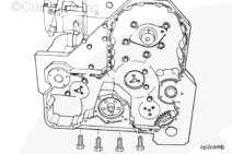
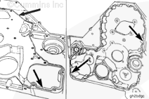
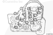
Remove the capscrews that secure the gear housing to the cylinder block.
NOTE: Be careful not to damage the oil pan gasket when removing the gear housing. If the gasket is damaged, the oil pan must be removed and the gasket replaced.
When using solvents, acids, or alkaline materials for cleaning, follow the manufacturer’s recommendations for use. Wear goggles and protective clothing to reduce the possibility of personal injury.
WARNING
When using a steam cleaner, wear safety glasses or a face shield, as well as protective clothing. Hot steam can cause serious personal injury.
WARNING
Wear appropriate eye and face protection when using compressed air. Flying debris and dirt can cause personal injury.
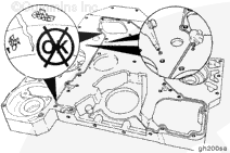
Avoid the use of excessive amounts of sealant, which could result in blocked oil passages in the engine and cause engine damage.
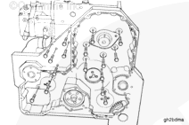
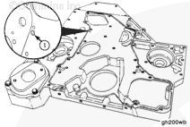
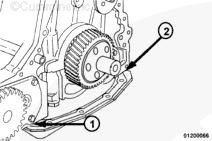
Install a new o-ring, Part Number 3883150, into the rear of the gear housing at the oil jumper gallery (1) for the accessory drive support. Be sure to keep sealant from the hole.
NOTE: Sealant requires assembly in 10 minutes or less. It is best to apply the sealant and then immediately assemble the parts.
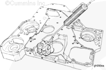
Apply a bead of sealant, Part Number 3164067, to the groove in the rear of the gear housing. Completely fill the groove so that approximately 1/16 to 1/8 inch of the bead is raised above the block mounting surface of the gear housing.
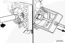
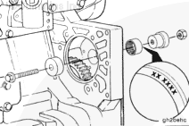
The bearing must be installed with the part number side of the bearing against the installation tool to prevent damage to the bearing during the installation.
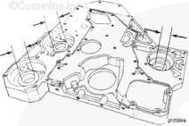
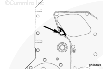
Use bearing driver kit, Part Number 3824117, to install a new needle bearing in the water pump drive bore of the gear housing.
Install the bearing from the front side of the gear housing, until the bearing is flush with the front edge of the housing bore.
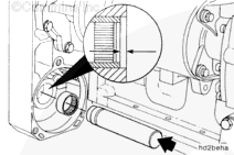
Use bearing installation tool, Part Number 3823776, included in bearing puller kit, Part Number 3823774, to install a new needle bearing in the hydraulic drive bore of the gear housing.
Tap the bearing gently until it comes in contact with the shoulder in the housing.
The bearing must be 0.25 to 0.76 mm [0.010 to 0.030 in] past the outside edge of the gear housing bore surface.
Hello, I'm Jack, a diesel engine fan and a blogger. I write about how to fix and improve diesel engines, from cars to trucks to generators. I also review the newest models and innovations in the diesel market. If you are interested in learning more about diesel engines, check out my blog and leave your feedback.
View all posts by Jack


 WARNING

 CAUTION

;)
;)
;)
;)
;)
;)
;)
;)
;)
;)
;)
;)
;)
;)
;)
;)
;)
;)
;)
;)
;)
;)
;)
;)
;)
;)
;)
;)
;)
;)