|
Fuel Pressure Sensor Circuit, Primary – Shorted Low
|

Overview
| CODE | REASON | EFFECT |
| Fault Code: 119 PID: P135 SPN: 135 FMI: 4 LAMP: Yellow SRT: |
Fuel pressure sensor, primary, shorted low. |
None. |
|
Fuel Pressure Sensor Circuit |
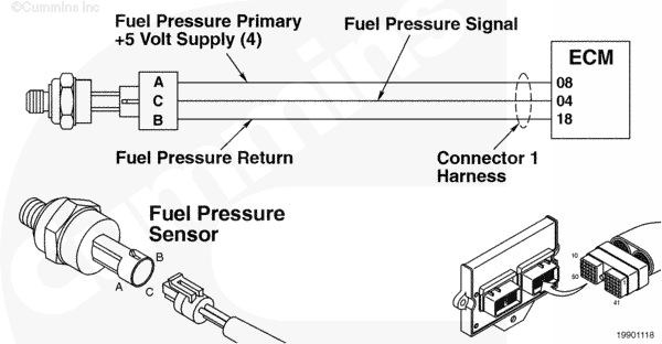 |
Circuit Description
The ECM uses this sensor to monitor the primary fuel pressure into the engine.
Component Location
The fuel pressure sensor is located in the low-pressure regulator housing.
Shop Talk
The fuel pressure sensor is used to detect the high-pressure fuel supplied to the engine from the OEM pressure regulator. The sensor is diagnostic only and does not affect fueling calculations to the engine. Disconnect the sensor before carrying out any wiring checks.
Cautions and Warnings
 CAUTION CAUTION To reduce the possibility of damaging a new ECM, all other active fault codes must be investigated prior to replacing the ECM. |
|
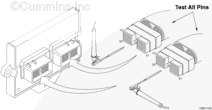
CAUTION To reduce the possibility of pin and harness damage, use the following test leads when taking a |
Troubleshooting Steps
| STEPS | SPECIFICATIONS | |
|---|---|---|
| STEP 1. | Check the fault codes. | |
| STEP 1A. Check for fault codes. | Fault Code 352 active? | |
| STEP 1B. Check for inactive fault codes. | Fault Code 119 inactive? | |
| STEP 2. | Check the fuel pressure sensor and circuit. | |
| STEP 2A. Inspect the fuel pressure sensor and connector pins. | Dirty or damaged pins? | |
| STEP 2B. Check the sensor supply voltage and return circuit. | 4.5 to 5.25 VDC? | |
| STEP 2C. Check the circuit response. | Fault Code 118 active and Fault Code 119 inactive? | |
| STEP 2D. Check the fault codes and verify sensor conditions. | Fault Code 119 active? | |
| STEP 3. | Check the ECM and engine harness. | |
| STEP 3A. Inspect the ECM and engine harness connector pins. | Dirty or damaged pins? | |
| STEP 3B. Check for an open circuit in the engine harness. | Less than 10 ohms? | |
| STEP 3C. Check for an open circuit in the engine harness. | Less than 10 ohms? | |
| STEP 3D. Check for a pin to pin short circuit in the engine harness. | Greater than 1000 ohms? | |
| STEP 3E. Check for a pin to pin short circuit to ground. | Greater than 100k ohms? | |
| STEP 3F. Check for an inactive fault code. | Fault Code 119 inactive? | |
| STEP 4. | Clear the fault codes. | |
| STEP 4A. Disable the fault code. | Fault Code 119 inactive? | |
| STEP 4B. Clear the inactive fault codes. | All fault codes cleared? | |
Guided Step 1 – Check the fault codes.
| Guided Step 1A – Check for Fault Code 386. | |
|---|---|
Conditions
Action
|
|
|
Fault Code 352 active? |
|
| YES | NO |
| No Repair | No Repair |
|
Fault Code 352
|
|
| Guided Step 1B – Check for an inactive fault code. | |
|---|---|
Conditions
Action
|
|
|
Fault Code 119 inactive? |
|
| YES | NO |
| No Repair | No Repair |
|
Procedure 019-362, Inactive or Intermittent Fault Code
|
|
Guided Step 2 – Check the fuel pressure sensor and circuit.
| Guided Step 2A – Inspect the fuel pressure sensor and connector pins. | |
|---|---|
Conditions
Action
For general inspection techniques, refer to Procedure 019-361, Component Connector and Pin Inspection. |
|
|
Dirty or damaged pins? |
|
| YES | NO |
|
Repair or replace the damaged engine harness, connector, or pins.
|
No Repair |
| Guided Step 2B – Check the sensor supply voltage and return circuit. | |
|---|---|
Conditions
Action
Refer to the wiring diagram for connection pin identification. |
|
|
4.5 to 5.25 VDC? |
|
| YES | NO |
| No Repair | No Repair |
| Guided Step 2C – Check the circuit response. | |
|---|---|
Conditions
Action
|
|
|
Fault Code 118 active and Fault Code 119 inactive? |
|
| YES | NO |
| No Repair | No Repair |
| Guided Step 2D – Check the fault codes and verify sensor condition. | |
|---|---|
Conditions
Action
|
|
|
Fault Code 119 active? |
|
| YES | NO |
|
Replace the fuel pressure sensor. Refer to Procedure 019-188. |
None, the removal and installation of the connector corrected the failure. |
Guided Step 3 – Check the ECM and engine harness.
| Guided Step 3A – Inspect the ECM and engine harness connector pins. | |
|---|---|
Conditions
Action
For general inspection techniques, refer to Procedure 019-361, Component Connector and Pin Inspection. |
|
|
Dirty or damaged pins? |
|
| YES | NO |
|
Repair or replace the engine harness, connector or pins. |
No Repair |
| Guided Step 3B – Check for an open circuit in the engine harness. | |
|---|---|
Conditions
Action
Refer to the wiring diagram for connector pin identification. For general resistance measurement techniques, refer to Procedure 019-360, Resistance Measurement Using a Multimeter and Wiring Diagram. |
|
|
Less than 10 ohms? |
|
| YES | NO |
| No Repair |
Repair or replace the engine harness. |
| Guided Step 3C – Check for an open circuit in the engine harness. | |
|---|---|
Conditions
Action
Refer to the wiring diagram for connector pin identification. For general resistance measurement techniques, refer to Procedure 019-360, Resistance Measurement Using a Multimeter and Wiring Diagram. |
|
|
Greater than 10 ohms? |
|
| YES | NO |
| No Repair |
Repair or replace the engine harness, connector or pins. |
| Guided Step 3D – Check for a pin to pin short circuit in the engine harness. | ||
|---|---|---|
Conditions
Action
Refer to the wiring diagram for connector pin identification. For general resistance measurement techniques, refer to Procedure 019-360, Resistance Measurement Using a Multimeter and Wiring Diagram. |
|
|
|
Greater than 1000 ohms? |
||
| YES | NO | |
| No Repair |
Repair or replace the engine harness, connector or pins. |
|
;)
;)
;)
;)
| Guided Step 3E – Check for a pin short circuit to ground. | |
|---|---|
Conditions
Action
Refer to the wiring diagram for connector pin identification. For general resistance measurement techniques, refer to Procedure 019-360, Resistance Measurement Using a Multimeter and Wiring Diagram. |
|
|
Greater than 100k ohms? |
|
| YES | NO |
| No Repair |
Repair or replace the engine harness, connector or pins. |
| Guided Step 3F – Check for an inactive fault code. | |
|---|---|
Conditions
Action
|
|
|
Fault Code 119 inactive? |
|
| YES | NO |
|
None, the removal and installation of the connector corrected the failure. |
Call for authorization prior to replacing the ECM. Replace the ECM. Refer to Procedure 019-031. |
Guided Step 4 – Clear the fault codes.
| Guided Step 4A – Disable the fault code. | |
|---|---|
Conditions
Action
|
|
|
Fault Code 119 inactive? |
|
| YES | NO |
| No Repair | No Repair |
| Guided Step 4B – Clear the inactive fault codes. | |
|---|---|
Conditions
Action
|
|
|
All fault codes cleared? |
|
| YES | NO |
| No Repair | No Repair |
|
Repair complete.
|
Appropriate troubleshooting charts
|