Overview
Fault Code: 121
PID: P190
SPN: 190
FMI: 10
LAMP: Yellow
SRT:
|
Invalid engine speed signal detected on the engine position sensor signal pins at the ECM connector.
|
Engine can die. Engine will not start.
|
|
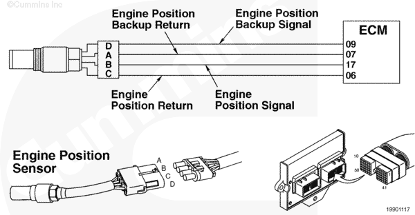
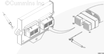
Engine Position Sensor Circuit |
|
|
Circuit Description
The engine position sensor monitors the engine position and speed, then passes this information to the ECM through the engine harness.
Component Location
The engine position sensor is located in the gear housing, above the air compressor.
Shop Talk
The engine position sensor is a magnetic sensor and senses the raised material on the back of the camshaft gear to determine engine position and speed.
Cautions and Warnings
 CAUTION
To reduce the possibility of damaging a new ECM, all other active fault codes must be investigated prior to replacing the ECM.
|
CAUTION
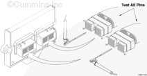
To reduce the possibility of pin and harness damage, use the appropriate test lead when taking a measurement.
|
CAUTION
To reduce the possibility of pin and harness damage, use the following test leads when taking a measurement:
Part Number 3822758 – male Deutsch/AMP/Metri-Pack test lead
Part Number 3823995 – male Weather-Pack test lead
Part Number 3823996 – female Weather-Pack test lead.
|
Troubleshooting Steps
| STEPS |
SPECIFICATIONS |
| STEP 1. |
Check the fault codes. |
|
| |
STEP 1A. Read the fault codes. |
Fault Code 121 active? |
| STEP 2. |
Check the engine position sensor. |
|
| |
STEP 2A. Inspect the engine harness and engine position sensor connector pins. |
Damaged or dirty pins? |
| |
STEP 2B. Inspect the sensor for damage. |
Damage found? |
| |
STEP 2C. Read the fault codes. |
Fault Code 121 active? |
| |
STEP 2D. Check the resistance of the sensor. |
1000 to 2000 ohms? |
| |
STEP 2E. Check for a short circuit to ground. |
More than 100k ohms? |
| STEP 3. |
Check the engine harness. |
|
| |
STEP 3A. Inspect the engine harness and ECM connector pins. |
Damaged or dirty pins? |
| |
STEP 3B. Read the fault codes. |
Fault Code 121 active? |
| |
STEP 3C. Check for an open circuit. |
Less than 10 ohms? |
| |
STEP 3D. Check for a short circuit to ground. |
More than 100k ohms? |
| |
STEP 3E. Check for a short circuit from pin to pin. |
More than 100k ohms? |
| STEP 4. |
Clear the fault codes. |
|
| |
STEP 4A. Disable the fault code. |
Fault Code 121 inactive? |
| |
STEP 4B. Clear the inactive fault codes. |
All fault codes cleared? |
Guided Step 1 – Check the fault codes.
| Guided Step 1A – Read the fault codes. |
Conditions
- Turn keyswitch ON
- Connect the INSITE™ electronic service tool.
Action
Use INSITE™ electronic service tool to read the fault codes.
|
|
Fault Code 121 active?
|
| YES |
NO |
| No Repair |
No Repair |
|
|
|
Guided Step 2 – Check the engine position sensor.
| Guided Step 2A – Inspect the engine harness and engine position sensor connector pins. |
Conditions
- Turn keyswitch OFF
- Disconnect the engine harness from the engine position sensor.
Action
- Corroded pins
- Bent or broken pins
- Pushed back or expanded pins
- Moisture in or on the connector
- Missing or damaged connector seals
- Dirt or debris in or on the connector pins.
|
|
Damaged or dirty pins?
|
| YES |
NO |
|
Repair the damaged pins. Repair or replace the engine harness or sensor, whichever has the damaged pins.
- Flush the dirt, debris, or moisture from the connector pins using electronic contact cleaner, Part Number 3824510.
- Install the appropriate connector seal if it is damaged or missing.
- Repair the engine harness. Refer to Procedure 019-201.
- Replace the engine harness. Refer to Procedure 019-043.
- Replace the sensor. Refer to Procedure 019-038.
|
No Repair |
|
|
|
| Guided Step 2B – Inspect the sensor for damage. |
Conditions
- Turn keyswitch OFF.
- Disconnect the engine harness from the engine position sensor.
Action
- Metal debris on end of sensor
- Damage to end of sensor caused by the engine gear
- Oil leakage or insulation problems such as swelling
- Damaged electrical potting in sensing end of sensor.
|
|
Damage found?
|
| YES |
NO |
|
Replace the sensor. Refer to Procedure 019-038.
|
No Repair |
|
|
|
| Guided Step 2C – Read the fault codes. |
Conditions
- Connect all components
- Turn keyswitch ON.
Action
- Start the engine and let it idle for one minute.
- Read the fault codes with INSITE™ electronic service tool.
|
|
Fault Code 121 active?
|
| YES |
NO |
| No Repair |
No Repair |
|
|
|
| Guided Step 2D – Check the resistance of the sensor. |
Conditions
- Turn keyswitch OFF.
- Disconnect the engine harness from the engine position sensor.
Action
- Measure the resistance from the engine position sensor positive pin to the engine position sensor negative pin in the engine position sensor connector.
- Measure the resistance from the engine position sensor backup positive pin to the engine position sensor backup negative pin in the engine position sensor connector.
|
|
|
1000 to 2000 ohms?
|
| YES |
NO |
| No Repair |
Replace the sensor. Refer to Procedure 019-038.
|
|
|
|
| Guided Step 2E – Check for a short circuit to ground. |
Conditions
- Turn keyswitch OFF
- Disconnect the engine harness from the engine position sensor
- Make sure the sensor is installed.
Action
- Measure the resistance from the engine position sensor positive pin in the engine position sensor connector, sensor side, to engine block ground.
- Measure the resistance from the engine position sensor backup positive pin in the engine position sensor connector, sensor side, to engine block ground.
|
|
|
More than 100k ohms?
|
| YES |
NO |
| No Repair |
Replace the sensor. Refer to Procedure 019-038.
|
|
|
|
Guided Step 3 – Check the engine harness.
| Guided Step 3A – Inspect the engine harness and ECM connector pins. |
Conditions
- Turn keyswitch OFF.
- Disconnect engine harness connector 1 from the ECM.
Action
- Corroded pins
- Bent or broken pins
- Pushed back or expanded pins
- Moisture in or on the connector
- Missing or damaged connector seals
- Dirt or debris in or on the connector pins.
|
|
Damaged or dirty pins?
|
| YES |
NO |
|
Repair the damaged pins. Repair or replace the engine harness, or replace the ECM, whichever has the damaged pins.
- Flush the dirt, debris, or moisture from the connector pins using electronic contact cleaner, Part Number 3824510.
- Install the appropriate connector seal if it is damaged or missing.
- Repair the engine harness. Refer to Procedure 019-204.
- Replace the engine harness. Refer to Procedure 019-043.
- Replace the ECM. Call for pre-authorization. Refer to Procedure 019-031.
|
No Repair |
|
|
|
| Guided Step 3B – Read the fault codes. |
Conditions
- Connect all components
- Turn keyswitch ON.
Action
- Start the engine and let it idle for one minute.
- Read the fault codes with INSITE™ electronic service tool.
|
|
Fault Code 121 active?
|
| YES |
NO |
| No Repair |
No Repair |
|
|
|
| Guided Step 3C – Check for an open circuit. |
Conditions
- Turn keyswitch OFF
- Disconnect the engine harness from the engine position sensor
- Disconnect engine harness connector 1 from the ECM.
Action
- Measure the resistance from the engine position sensor positive pin in the engine harness sensor connector to the engine position sensor positive pin in the engine harness ECM connector.
- Measure the resistance from the engine position sensor backup positive pin in the engine harness sensor connector to the engine position sensor backup positive pin in the engine harness ECM connector.
- Measure the resistance from the engine position sensor negative pin in the engine harness sensor connector to the engine position sensor negative pin in the engine harness ECM connector.
- Measure the resistance from the engine position sensor backup negative pin in the engine harness sensor connector to the engine position sensor backup negative pin in the engine harness ECM connector.
|
|
|
Less than 10 ohms?
|
| YES |
NO |
| No Repair |
Repair or replace the engine harness.
- Repair the engine harness. Refer to Procedure 019-201 or 019-204.
- Replace the engine harness. Refer to Procedure 019-043.
|
|
|
|
| Guided Step 3D – Check for a short circuit to ground. |
Conditions
- Turn keyswitch off
- Disconnect the engine harness from the engine position sensor
- Disconnect the engine harness connector 1 from the ECM.
Action
- Measure the resistance from the engine position sensor positive pin in the engine harness ECM connector to the engine block ground.
- Measure the resistance from the engine position sensor backup positive pin in the engine harness ECM connector to the engine block ground.
- Refer to the circuit diagram or wiring diagram for connector pin identification.
|
|
|
More than 100k ohms?
|
| YES |
NO |
| No Repair |
Repair or replace the engine harness.
- Repair the engine harness. Refer to Procedure 019-204.
- Replace the engine harness. Refer to Procedure 019-043.
|
|
|
|
| Guided Step 3E – Check for a short circuit from pin to pin. |
Conditions
- Turn keyswitch off
- Disconnect the engine harness from the engine position sensor
- Disconnect the engine harness connector 1 and connector 2 from the ECM.
Action
- Measure the resistance from the engine position sensor positive pin in the engine harness ECM connector 1 to all other pins in the connector.
- Measure the resistance from the engine position sensor positive pin in the engine harness ECM connector 1 to all the pins in engine harness connector 2.
- Measure the resistance from the engine position sensor backup positive pin in the engine harness ECM connector 1 to all other pins in the connector.
- Measure the resistance from the engine position sensor backup positive pin in the engine harness ECM connector 1 to all the pins in engine harness connector 2.
- Refer to the circuit diagram or wiring diagram for connector pin identification.
|
|
|
More than 100k ohms?
|
| YES |
NO |
| No Repair |
Repair or replace the engine harness.
- Repair the engine harness. Refer to Procedure 019-204.
- Replace the engine harness. Refer to Procedure 019-043.
|
|
|
|
Guided Step 4 – Clear the fault codes.
| Guided Step 4A – Disable the fault code. |
Conditions
- Connect all components
- Turn keyswitch ON.
Action
- Start the engine and let it idle for one minute.
- Verify that Fault Code 121 is inactive.
|
|
Fault Code 121 inactive?
|
| YES |
NO |
| No Repair |
Troubleshooting procedures need to be repeated from the beginning.
|
|
|
|
| Guided Step 4B – Clear the inactive fault codes. |
Conditions
- Connect all components
- Turn keyswitch ON.
Action
- Use INSITE™ electronic service tool to erase the inactive fault codes.
|
|
All fault codes cleared?
|
| YES |
NO |
| No Repair |
Troubleshoot any remaining active fault codes.
|
|
Repair complete
|
Appropriate troubleshooting charts
|
Last Modified: 06-Aug-2004

;)
;)
;)
;)
;)
;)
;)
;)
;)
;)
;)
;)