Overview
Fault Code: 242
PID: P84
SPN: 84
FMI: 10
LAMP: Amber
SRT:
|
Invalid vehicle speed signal detected; signal tampered.
|
Maximum engine speed is limited to the value set for maximum engine speed without the vehicle speed sensor. Cruise controller and road speed governor will not work.
|
|
Vehicle Speed Sensor Circuit |
|
|
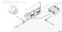
Circuit Description
The vehicle speed sensor is an OEM-supplied sensor but can provide an input to the electronic control module (ECM) for added features such as road speed governing and cruise control.
Component Location
Refer to the OEM manual for location of this sensor. Usually, this sensor is installed in the tailshaft of the transmission.
Shop Talk
- Disconnect the vehicle speed sensor connector that connects to the OEM speedometer, or trip recorder, and move the vehicle. If the fault goes inactive, there is probably electrical noise being fed into the vehicle speed sensor circuit from the OEM device.
- Verify the vehicle speed sensor wires in the OEM harness are twisted pairs.
- This sensor usually has one coil but can have two. Only one is used for engine control.
Cautions and Warnings
 CAUTION
To reduce the possibility of damaging a new ECM, all other active fault codes must be investigated prior to replacing the ECM.
|
CAUTION
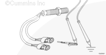
To reduce the possibility of pin and harness damage, use the following test leads when taking a measurement:
Part Number 3822758 – male Deutsch/AMP/Metri-Pack test lead
Part Number 3823996 – female Weather-Pack test lead.
|
Troubleshooting Steps
| STEPS |
SPECIFICATIONS |
| STEP 1. |
Verify vehicle speed settings. |
|
| |
STEP 1A. Check vehicle speed settings with INSITE™. |
Trim sets correct? |
| STEP 2. |
Check the vehicle speed sensor. |
|
| |
STEP 2A. Inspect the OEM harness and sensor connector pins. |
Dirty or damaged pins? |
| |
STEP 2B. Read the fault codes. |
Fault Code 242 active? |
| |
STEP 2C. Check the vehicle speed sensor for proper adjustment. |
1/2 to 3/4 of a turn out from the gear? |
| |
STEP 2D. Check the vehicle speed sensor resistance. |
750 to 1500 ohms? |
| |
STEP 2E. Check the vehicle speed sensor for a short circuit to ground. |
Greater than 100k ohms? |
| |
STEP 2F. Check the vehicle speed sensor for a short circuit between coils. |
Greater than 100k ohms? |
| STEP 3. |
Check the OEM harness. |
|
| |
STEP 3A. Inspect the OEM harness connector pins. |
Dirty or damaged pins? |
| |
STEP 3B. Read the fault codes. |
Fault Code 242 active? |
| |
STEP 3C. Check for an open circuit. |
Less than 10 ohms? |
| |
STEP 3D. Check for a short circuit to ground. |
Greater than 100k ohms? |
| |
STEP 3E. Check for a short circuit from pin to pin. |
Greater than 100k ohms? |
| STEP 4. |
Check the engine harness. |
|
| |
STEP 4A. Inspect the engine harness and ECM connector pins. |
Dirty or damaged pins? |
| |
STEP 4B. Read the fault codes. |
Fault Code 242 active? |
| |
STEP 4C. Check for an open circuit. |
Less than 10 ohms? |
| |
STEP 4D. Check for a short circuit to ground. |
Greater than 100k ohms? |
| |
STEP 4E. Check for a short circuit from pin to pin. |
Greater than 100k ohms? |
| STEP 5. |
Clear the fault codes. |
|
| |
STEP 5A. Disable the fault code. |
Fault Code 242 inactive? |
| |
STEP 5B. Clear the inactive fault codes. |
All fault codes cleared? |
Guided Step 1 – Verify vehicle speed settings.
| Guided Step 1A – Check vehicle speed settings with INSITE™ electronic service tool. |
Conditions
- Turn keyswitch ON
- Connect INSITE™ electronic service tool.
Action
- Check that the vehicle speed settings are correct.
- Compare the vehicle speed on the bus is in relationship to the INSITE™ electronic service tool reading for vehicle speed.
|
|
Trim sets correct?
|
| YES |
NO |
| No Repair |
Adjust settings to vehicle specification. Refer to the OEM manual.
|
|
|
|
Guided Step 2 – Check the vehicle speed sensor.
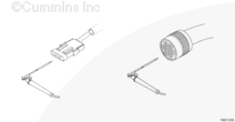
| Guided Step 2A – Inspect the OEM harness and sensor connector pins. |
Conditions
- Turn keyswitch OFF
- Disconnect the OEM harness from the vehicle speed sensor.
Action
- Corroded pins
- Bent or broken pins
- Pushed back or expanded pins
- Wire insulation damaged
- Moisture in or on the connector
- Missing or damaged connector seals
- Connector shell broken
- Dirt or debris in or on the connector pins.
For general inspection techniques, refer to Component Connector Pin Inspection, Procedure 019-361.
|
|
Dirty or damaged pins?
|
| YES |
NO |
|
Repair the damaged pins.
Repair or replace the OEM harness, or replace the sensor, whichever has the damaged pins.
- Flush the dirt, debris, or moisture from the connector pins using electronic contact cleaner, Part Number 3824510.
- Install the appropriate connector seal if it is damaged or missing.
- Repair the OEM harness. Refer to OEM troubleshooting and rep[air manaul.
- Replace the OEM harness. Refer to OEM troubleshooting and rep[air manaul.
- Replace the sensor. Refer to Procedure 019-090 or 019-091.
|
No Repair |
|
|
|
| Guided Step 2B – Read the fault codes. |
Conditions
- Connect all components
- Turn keyswitch ON
- Connect INSITE™ electronic service tool.
Action
- Start the engine and let it idle for one minute.
- Use INSITE™ electronic service tool to read the fault codes.
|
|
Fault Code 242 active?
|
| YES |
NO |
| No Repair |
No Repair |
|
|
|
| Guided Step 2C – Check the vehicle speed sensor for proper adjustment. |
Conditions
- Turn keyswitch OFF
- Disconnect the OEM harness from the vehicle speed sensor.
Action
- Verify that the vehicle speed sensor is adjusted properly.
|
|
1/2 to 3/4 of a turn out from the gear?
|
| YES |
NO |
| No Repair |
Adjust the sensor. Refer to Procedure 019-090 or 019-091.
|
|
|
|
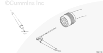
| Guided Step 2D – Check the vehicle speed sensor resistance. |
Conditions
- Turn keyswitch OFF
- Disconnect the OEM harness from the vehicle speed sensor.
Action
- Measure the resistance from the (+) pin to the (-) pin in the vehicle speed sensor connector, sensor side.
- Repeat the resistance check in the second coil (if applicable).
|
|
|
750 to 1500 ohms?
|
| YES |
NO |
| No Repair |
Replace the sensor. Refer to Procedure 019-090 or 019-091.
|
|
|
|
| Guided Step 2E – Check the vehicle speed sensor for a short circuit to ground. |
Conditions
- Turn keyswitch OFF
- Disconnect the OEM harness from the vehicle speed sensor.
Action
- Measure the resistance from the (+) pin in the vehicle speed sensor connector, sensor side, to engine block ground.
- Repeat the short-circuit-to-ground check in the second coil (if applicable).
|
|
|
Greater than 100k ohms?
|
| YES |
NO |
| No Repair |
Replace the sensor. Refer to Procedure 019-090 or 019-091.
|
|
|
|
| Guided Step 2F – Check the vehicle speed sensor for a short circuit between coils. |
Conditions
- Turn keyswitch OFF
- Disconnect the OEM harness from the vehicle speed sensor.
Action
- Measure the resistance from the (+) pin in the vehicle speed sensor connector to the (+) pin in the second vehicle speed sensor connector, sensor side.
|
|
|
Greater than 100k ohms?
|
| YES |
NO |
| No Repair |
Replace the sensor. Refer to Procedure 019-090 or 019-091.
|
|
|
|
Guided Step 3 – Check the OEM harness.
| Guided Step 3A – Inspect the OEM harness connector pins. |
Conditions
- Turn keyswitch OFF
- Disconnect the engine harness from the OEM harness at the 31 pin OEM connector.
Action
- Corroded pins
- Bent or broken pins
- Pushed back or expanded pins
- Wire insulation damaged
- Moisture in or on the connector
- Missing or damaged connector seals
- Connector shell broken
- Dirt or debris in or on the connector pins.
For general inspection techniques, refer to Component Connector Pin Inspection, Procedure 019-361.
|
|
Dirty or damaged pins?
|
| YES |
NO |
|
Repair the damaged pins.
Repair or replace the OEM harness, or replace the sensor, whichever has the damaged pins.
- Flush the dirt, debris, or moisture from the connector pins using electronic contact cleaner, Part Number 3824510.
- Install the appropriate connector seal if it is damaged or missing.
- Repair the OEM harness. Refer to OEM troubleshooting and rep[air manaul.
- Replace the OEM harness. Refer to OEM troubleshooting and rep[air manaul.
|
No Repair |
|
|
|
| Guided Step 3B – Read the fault codes. |
Conditions
- Connect all components
- Turn keyswitch ON
- Connect INSITE™ electronic service tool.
Action
- Start the engine and let it idle for one minute.
- Use INSITE™ electronic service tool to read the fault codes.
|
|
Fault Code 242 active?
|
| YES |
NO |
| No Repair |
No Repair |
|
|
|
| Guided Step 3C – Check for an open circuit. |
Conditions
- Turn keyswitch OFF
- Disconnect the engine harness from the OEM harness at the 31-pin OEM connector
- Disconnect the OEM harness from the vehicle speed sensor.
Action
- Measure the resistance from the vehicle speed sensor (+) pin in the OEM harness sensor connector to the vehicle speed sensor (+) pin in the 31-pin OEM connector, OEM harness side.
- Measure the resistance from the vehicle speed sensor (-) pin in the OEM harness sensor connector to the vehicle speed sensor (-) pin in the 31-pin OEM connector, OEM harness side.
|
|
|
Less than 10 ohms?
|
| YES |
NO |
| No Repair |
Repair or replace the OEM harness. Refer to the OEM troubleshooting and repair manual.
|
|
|
|
| Guided Step 3D – Check for a short circuit to ground. |
Conditions
- Turn keyswitch OFF
- Disconnect the engine harness from the OEM harness at the 31-pin OEM connector
- Disconnect the OEM harness from the vehicle speed sensor.
Action
- Measure the resistance from the vehicle speed sensor (+) pin in the 31-pin OEM connector, OEM harness side, to engine block ground.
|
|
|
Greater than 100k ohms?
|
| YES |
NO |
| No Repair |
Repair or replace the OEM harness. Refer to the OEM troubleshooting and repair manual.
|
|
|
|
| Guided Step 3E – Check for a short circuit from pin to pin. |
Conditions
- Turn keyswitch OFF
- Disconnect the engine harness from the OEM harness at the 31-pin OEM connector
- Disconnect the OEM harness from the vehicle speed sensor.
Action
- Measure the resistance from the vehicle speed sensor (+) pin in the 31-pin OEM connector, OEM harness side, to all other pins in the connector.
- Measure the resistance from the vehicle speed sensor (-) pin in the 31-pin OEM connector, OEM harness side, to all other pins in the connector.
|
|
|
Greater than 100k ohms?
|
| YES |
NO |
| No Repair |
Repair or replace the OEM harness. Refer to the OEM troubleshooting and repair manual.
|
|
|
|
Guided Step 4 – Check the engine harness.
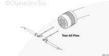
| Guided Step 4A – Inspect the engine harness and ECM connector pins. |
Conditions
- Turn keyswitch OFF
- Disconnect engine harness connector 1 and connector 2 from the ECM.
Action
- Corroded pins
- Bent or broken pins
- Pushed back or expanded pins
- Wire insulation damaged
- Moisture in or on connector
- Missing or damaged connector seals
- Connector shell broken
- Dirt or debris in or on the connector pins.
Refer to the circuit diagram or wiring diagram for component pin identification.
For general inspection techniques, refer to Component Connector and Pin Inspection, Procedure 019-361.
|
|
Dirty or damaged pins?
|
| YES |
NO |
|
Repair the damaged pins.
Repair or replace the engine harness, or replace the ECM, whichever has the damaged pins.
- Flush the dirt, debris, or moisture from the connector pins using electronic contact cleaner, Part Number 3824510.
- Install the appropriate connector seal if it is damaged or missing.
- Repair the engine harness. Refer to Procedure 019-204.
- Replace the engine harness. Refer to Procedure 019-043.
- Replace the ECM. Call for pre-authorization. . Refer to Procedure 019-031.
|
No Repair |
|
|
|
| Guided Step 4B – Read the fault codes. |
Conditions
- Connect all components
- Turn keyswitch ON
- Connect INSITE™ electronic service tool.
Action
- Start the engine and let it idle for one minute.
- Use INSITE™ electronic service tool to read the fault codes.
|
|
Fault Code 242 active?
|
| YES |
NO |
| No Repair |
No Repair |
|
|
|
| Guided Step 4C – Check for an open circuit. |
Conditions
- Turn keyswitch OFF
- Disconnect engine harness connector 2 from the ECM
- Disconnect the engine harness from the OEM harness at the 31-pin OEM connector.
Action
- Measure the resistance from the vehicle speed sensor (+) pin in the engine harness ECM connector to the vehicle speed sensor (+) pin in the 31-pin OEM connector, engine harness side.
- Measure the resistance from the vehicle speed sensor (-) pin in the engine harness ECM connector to the vehicle speed sensor (-) pin in the 31-pin OEM connector, engine harness side.
|
|
|
Less than 10 ohms?
|
| YES |
NO |
| No Repair |
Repair the damaged pins.
Repair or replace the engine harness, whichever has the damaged pins.
- Flush the dirt, debris, or moisture from the connector pins using electronic contact cleaner, Part Number 3824510.
- Install the appropriate connector seal if it is damaged or missing.
- Repair the engine harness. Refer to Procedure 019-208 or 019-204.
- Replace the engine harness. Refer to Procedure 019-043.
|
|
|
|
| Guided Step 4D – Check for a short circuit to ground. |
Conditions
- Turn keyswitch OFF
- Disconnect engine harness connector 2 from the ECM
- Disconnect the engine harness from the OEM harness at the 31-pin OEM connector.
Action
- Measure the resistance from the vehicle speed sensor (+) pin in the engine harness ECM connector to engine block ground.
|
|
|
Greater than 100k ohms?
|
| YES |
NO |
| No Repair |
Repair the damaged pins.
Repair or replace the engine harness, whichever has the damaged pins.
- Flush the dirt, debris, or moisture from the connector pins using electronic contact cleaner, Part Number 3824510.
- Install the appropriate connector seal if it is damaged or missing.
- Repair the engine harness. Refer to Procedure 019-204.
- Replace the engine harness. Refer to Procedure 019-043.
|
|
|
|
| Guided Step 4E – Check for a short circuit from pin to pin. |
Conditions
- Turn keyswitch OFF
- Disconnect engine harness connector 1 and connector 2 from the ECM
- Disconnect the engine harness from the OEM harness at the 23-pin and 31-pin OEM connectors.
Action
- Measure the resistance from the vehicle speed sensor (+) pin in engine harness ECM connector 2 to all other pins in the connector.
- Measure the resistance from the vehicle speed sensor (-) pin in engine harness ECM connector 2 to all other pins in the connector.
- Measure the resistance from the vehicle speed sensor (+) pin in engine harness ECM connector 2 to all pins in engine harness ECM connector 1.
- Measure the resistance from the vehicle speed sensor (-) pin in engine harness ECM connector 2 to all pins in engine harness ECM connector 1.
|
|
|
Greater than 100k ohms?
|
| YES |
NO |
| No Repair |
Repair the damaged pins.
Repair or replace the engine harness, whichever has the damaged pins.
- Flush the dirt, debris, or moisture from the connector pins using electronic contact cleaner, Part Number 3824510.
- Install the appropriate connector seal if it is damaged or missing.
- Repair the engine harness. Refer to Procedure 019-204.
- Replace the engine harness. Refer to Procedure 019-043.
|
|
|
|
Guided Step 5 – Clear the fault code.
| Guided Step 5A – Disable the fault code. |
Conditions
- Connect all components
- Turn keyswitch ON
- Connect INSITE™ electronic service tool.
Action
- Start the engine and let it idle for one minute.
- Drive the vehicle at a set speed and verify speed using INSITE™ electronic service tool.
- Use INSITE™ electronic service tool to verify the fault code is inactive.
|
|
Fault Code 242 inactive?
|
| YES |
NO |
| No Repair |
Troubleshooting procedures need to be repeated from the beginning.
|
|
|
|
| Guided Step 4B – Clear the inactive fault codes. |
Conditions
- Connect all components
- Turn keyswitch ON
- Connect INSITE™ electronic service tool.
Action
- Use INSITE™ electronic service tool to erase the inactive fault codes.
|
|
All fault codes cleared?
|
| YES |
NO |
| No Repair |
Troubleshoot any remaining active fault codes.
|
|
Repair complete
|
Appropriate troubleshooting steps
|
Last Modified: 28-Sep-2004


;)
;)
;)
;)
;)
;)
;)
;)
;)
;)
;)
;)
;)
;)
;)
;)
;)
;)
;)
;)