|
Compressor Inlet Temperature Sensor Circuit – Shorted Low
|

Overview
Compressor Inlet Temperature Sensor Circuit – Shorted Low
| CODE | REASON | EFFECT |
| Fault Code: 256 PID: P171 SPN: 171 FMI: 4 LAMP: Amber SRT: |
Compressor Inlet Temperature Sensor Circuit – Voltage below normal, or Shorted to low source. Low signal voltage detected on the compressor inlet circuit at the ECM. |
Possible reduced engine performance. Fan will stay ON if controlled by ECM. No engine protection for compressor inlet temperature. |
|
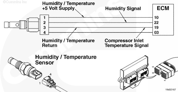
Compressor Inlet Temperature Sensor Circuit |
 |
;)
;)
Circuit Description
The electronic control module (ECM) uses the compressor inlet temperature sensor input to determine the temperature of the air entering the turbocharger.
Component Location
The compressor inlet temperature sensor is located in the intake piping to the turbocharger (combination sensor with humidity).
Shop Talk
- The compressor inlet temperature sensor is a combination sensor with the humidity sensor.
All temperature sensors:
- The resistance of the sensor varies with temperature. The reading observed must compare to the following table if the sensor is functioning properly.
| Temperature (°C) | Temperature (°F) | Resistance (ohms) |
| 0 | 32 | 30k to 36k |
| 25 | 77 | 9k to 11k |
| 50 | 122 | 3k to 4k |
| 75 | 167 | 1350 to 1500 |
| 100 | 212 | 600 to 675 |
Cautions and Warnings
 CAUTION CAUTION To reduce the possibility of damaging a new ECM, all other active fault codes must be investigated prior to replacing the ECM. |
|
CAUTION To reduce the possibility of pin and harness damage, use the following test leads when taking a measurement: |
Troubleshooting Steps
| STEPS | SPECIFICATIONS | |
|---|---|---|
| STEP 1. | Check the fault codes. | |
| STEP 1A. Check for an inactive fault code. | Fault Code 256 inactive? | |
| STEP 2. | Check the compressor inlet temperature sensor and circuit. | |
| STEP 2A. Inspect the compressor inlet temperature sensor and connector pins. | Dirty or damaged pins? | |
| STEP 2B. Check the circuit response. | Fault Code 249 active and Fault Code 256 inactive? | |
| STEP 2C. Check for circuit response | Fault Code 256 active? | |
| STEP 3. | Check the ECM and engine harness. | |
| STEP 3A. Inspect the ECM and engine harness connector pins. | Dirty or damaged pins? | |
| STEP 3B. Check for a pin to pin short circuit in the engine harness. | Greater than 100k ohms? | |
| STEP 3C. Check for a pin short to ground. | Greater than 100k ohms? | |
| STEP 3D. Check for an inactive fault code. | Fault Code 256 inactive? | |
| STEP 4. | Clear the fault codes. | |
| STEP 4A. Disable the fault code. | Fault Code 249 inactive? | |
| STEP 4B. Clear the inactive fault codes. | All fault codes cleared? | |
Guided Step 1 – Check the fault codes.
| Guided Step 1A – Check for an inactive fault code. | |
|---|---|
Conditions
ActionCheck for an inactive fault code. Use INSITE™ electronic service tool to read the fault codes. |
|
|
Fault Code 256 inactive? |
|
| YES | NO |
| No Repair | No Repair |
Guided Step 2 – Check the compressor inlet temperature sensor and circuit.
| Guided Step 2A – Inspect the compressor inlet temperature sensor and connector pins. | |
|---|---|
Conditions
ActionInspect the engine harness and compressor inlet temperature sensor connector pins for the following:
For general inspection techniques, refer to Component Connector and Pin Inspection, Procedure 019-361. |
|
|
Dirty damaged pins? |
|
| YES | NO |
|
A defective connection has been detected in the sensor or harness connector. Repair the damaged pins. Repair or replace the engine harness, whichever has the damaged pins. |
No Repair |
| Guided Step 2B – Check the circuit response. | |
|---|---|
Conditions
ActionCheck for the appropriate circuit response after 30 seconds.
|
|
|
Fault Code 249 active and Fault Code 256 inactive? |
|
| YES | NO |
| No Repair | No Repair |
| Guided Step 2C – Check the fault codes and verify sensor condition. | |
|---|---|
Conditions
ActionCheck for the appropriate circuit response after 30 seconds.
|
|
|
Fault Code 256 active? |
|
| YES | NO |
|
A defective sensor has been detected. Replace the humidity/temperature sensor. Refer to Procedure 019-356. |
No Repair |
Guided Step 3 – Check the ECM and engine harness.
| Guided Step 3A – Inspect the engine harness and ECM connector pins. | |
|---|---|
Conditions
ActionInspect the engine harness and ECM connector 1 pins for the following:
For general inspection techniques, refer to Component Connector and Pin Inspection, Procedure 019-361. |
|
|
Dirty damaged pins? |
|
| YES | NO |
|
A defective connection has been detected in the ECM connector or engine harness connector. Repair the damaged pins. Repair or replace the engine harness, whichever has the damaged pins. |
No Repair |
| Guided Step 3B – Check for a pin to pin short circuit in the engine harness. | |
|---|---|
Conditions
ActionCheck for a pin to pin short.
Refer to the circuit diagram or wiring diagram for component pin identification. For general inspection techniques, refer to Component Connector and Pin Inspection, Procedure 019-360. |
|
|
Greater than 100k ohms? |
|
| YES | NO |
| No Repair |
A pin to pin short circuit on the SIGNAL line has been detected in the engine harness Repair or replace the engine harness, whichever has the damaged pins. |
| Guided Step 3C – Check for a pin short circuit to ground. | |
|---|---|
Conditions
ActionCheck for a pin to ground short.
Refer to the circuit diagram or wiring diagram for connector pin identification. For general resistance measurement techniques, refer to Measurements Using a Multimeter and Wiring Diagram, Procedure 019-360. |
|
|
Greater than 100k ohms? |
|
| YES | NO |
| No Repair |
A pin to pin to ground short circuit on the SIGNAL line has been detected in the engine harness. Repair or replace the engine harness. |
| Guided Step 3D – Check for an inactive fault code. | |
|---|---|
Conditions
ActionCheck for the appropriate circuit response after 30 seconds. Use INSITE™ electronic service tool to read the fault codes. |
|
|
Fault Code 256 inactive? |
|
| YES | NO |
| No Repair |
Replace the ECM. Call for pre-authorization. Refer to Procedure 019-031. |
Guided Step 4 – Clear the fault codes.
| Guided Step 4A – Disable the fault code. | |
|---|---|
Conditions
ActionDisable the fault code.
|
|
|
Fault Code 256 inactive? |
|
| YES | NO |
| No Repair | No Repair |
| Guided Step 4B – Clear the inactive fault codes. | |
|---|---|
Conditions
ActionClear the inactive fault codes.
|
|
|
All fault codes cleared? |
|
| YES | NO |
| No Repair | No Repair |
|
Repair complete
|
Appropriate troubleshooting charts
|