|
Humidity Sensor – Voltage Below Normal
|

Overview
| CODE | REASON | EFFECT |
| Fault Code: 1129 PID: 370 SPN: 2946 FMI: 4 LAMP: Amber SRT: |
Humidity Sensor – Voltage below normal or shorted to a low source. Low signal voltage detected at the humidity sensor signal circuit at the ECM. |
Possible reduced performance. |
|
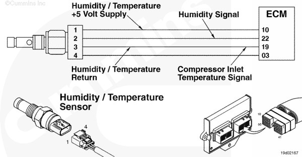
Humidity Sensor Circuit |
 |
;)
;)
Circuit Description
The electronic control module (ECM) uses the humidity sensor to measure relative humidity. The humidity sensor is connected to sensor supply number 1.
Component Location
The humidity sensor is located in the turbocharger compressor inlet elbow.
Shop Talk
Relative humidity is calculated using the turbocharger compressor temperature sensor, turbocharger compressor pressure sensor, and humidity sensor. The units are displayed in grains/pound mass of dry air. The humidity sensor can only provide a valid reading under certain engine operating conditions. The value displayed for specific humidity is the last value updated by the sensor. A value of 75 grains is the default and will be displayed until the engine operating conditions are met for an update.
Cautions and Warnings
 CAUTION CAUTION To reduce the possibility of damaging a new ECM, all other active fault codes must be investigated prior to replacing the ECM. |
|
CAUTION To reduce the possibility of pin and harness damage, use the following test leads when taking a measurement: |
Troubleshooting Steps
| STEPS | SPECIFICATIONS | |
|---|---|---|
| STEP 1. | Check the fault codes. | |
| STEP 1A. Check for sensor supply fault codes. | Fault Code 352 or 386 active? | |
| STEP 1B. Read the fault codes. | Fault Code 1129 active? | |
| STEP 2. | Check the humidity sensor and circuit. | |
| STEP 2A. Inspect the humidity sensor and connector pins. | Dirty or damaged pins? | |
| STEP 2B. Check the sensor supply voltage and return circuit. | 4.5 to 5.3 VDC? | |
| STEP 2C. Check the circuit response. | Fault Code 1128 active and Fault Code 1129 inactive? | |
| STEP 2D. Check the fault codes and verify sensor condition. | Fault Code 1129 active? | |
| STEP 3. | Check the ECM and engine harness. | |
| STEP 3A. Inspect the ECM and engine harness connector pins. | Dirty or damaged pins? | |
| STEP 3B. Check for an open circuit in the engine harness. | Less than 10 ohms? | |
| STEP 3C. Check for an open circuit in the engine harness. | Less than 10 ohms? | |
| STEP 3D. Check for a pin-to-pin short circuit in the engine harness. | Greater than 100k ohms? | |
| STEP 3E. Check for a pin short circuit to ground. | Greater than 100k ohms? | |
| STEP 3F. Check for an inactive fault code. | Fault Code 1129 inactive? | |
| STEP 4. | Clear the fault codes. | |
| STEP 4A. Disable the fault code. | Fault Code 1129 inactive? | |
| STEP 4B. Clear the inactive fault codes. | All fault codes cleared? | |
Guided Step 1 – Check the fault codes.
| Guided Step 1A – Check for sensor supply fault codes. | |
|---|---|
Conditions
Action
|
|
|
Fault Codes 352 and/or 386 active? |
|
| YES | NO |
| No Repair | No Repair |
|
Fault Code 352 and/or 386
|
|
| Guided Step 1B – Check the fault codes. | |
|---|---|
Conditions
Action
|
|
|
Fault Code 1129 active? |
|
| YES | NO |
| No Repair | No Repair |
|
Procedure 019-361
|
|
Guided Step 2 – Check the humidity sensor and circuit.
| Guided Step 2A – Inspect the humidity sensor and connector pins. | |
|---|---|
Conditions
Action
For general inspection techniques, refer to Component Connector and Pin Inspection, Procedure 019-361. |
|
|
Dirty or damaged pins? |
|
| YES | NO |
|
A defective connection has been detected in the sensor or harness connector. Clean the connector and pins. Repair the damaged harness, connector, or pins if possible. Refer to Procedure 019-043 Refer to Procedure 019-218. Refer to Procedure 019-356. |
No Repair |
| Guided Step 2B – Check the sensor supply voltage and return circuit. | |
|---|---|
Conditions
Action
Refer to the circuit diagram or wiring diagram for connector pin identification. |
|
|
4.5 to 5.3 VDC? |
|
| YES | NO |
| No Repair | No Repair |
| Guided Step 2C – Check the circuit response. | |
|---|---|
Conditions
Action
|
|
|
Fault Code 1128 active and Fault Code 1129 inactive? |
|
| YES | NO |
| No Repair | No Repair |
| Guided Step 2D – Check the fault codes and verify sensor condition. | |
|---|---|
Conditions
Action
|
|
|
Fault Code 1129 active? |
|
| YES | NO |
|
A defective sensor has been detected. Replace the humidity sensor. Refer to procedure 019-356. |
None. The removal and installation of the connector corrected the failure. |
Guided Step 3 – Check the ECM and engine harness.
| Guided Step 3A – Inspect ECM and engine harness connector pins. | |
|---|---|
Conditions
Action
For general inspection techniques, refer to Component Connector and Pin Inspection, Procedure 019-361. |
|
|
Dirty or damaged pins? |
|
| YES | NO |
|
A defective connection has been detected in the ECM or engine harness connector. Clean the connector and pins. Repair the damaged harness, connector or pins if possible. Refer to Procedure 019-043. Refer to Procedure 019-204. Refer to Procedure 019-031. |
No Repair |
| Guided Step 3B – Check for an open circuit in the engine harness. | |
|---|---|
Conditions
Action
Refer to the circuit diagram or wiring diagram for connector pin identification. For general resistance measurement techniques, refer to Resistance Measurements Using a Multimeter and Wiring Diagram, Procedure 019-360. |
|
|
Less than 10 ohms? |
|
| YES | NO |
| No Repair |
An open supply circuit has been detected in the engine harness. Repair or replace the engine harness. Refer to Procedure 019-204. Refer to Procedure 019-043. |
| Guided Step 3C – Check for an open circuit in the engine harness. | |
|---|---|
Conditions
Action
Refer to the circuit diagram or wiring diagram for connector pin identification. For general resistance measurement techniques, refer to Resistance Measurements Using a Multimeter and Wiring Diagram, Procedure 019-360. |
|
|
Less than 10 ohms? |
|
| YES | NO |
| No Repair |
An open signal circuit has been detected in the engine harness. Repair or replace the engine harness. Refer to Procedure 019-204. Refer to Procedure 019-043. |
| Guided Step 3D – Check for a pin-to-pin short in the engine harness. | |
|---|---|
Conditions
Action
Refer to the circuit diagram or wiring diagram for connector pin identification. For general resistance measurement techniques, refer to Resistance Measurements Using a Multimeter and Wiring Diagram, Procedure 019-360. |
|
|
Greater than 100K ohms? |
|
| YES | NO |
| No Repair |
A pin-to-pin short circuit on the signal line has been detected in the engine harness. Repair or replace the engine harness. Refer to Procedure 019-204. Refer to Procedure 019-043. |
| Guided Step 3E – Check for a pin short circuit to ground. | |
|---|---|
Conditions
Action
Refer to the circuit diagram or wiring diagram for connector pin identification. For general resistance measurement techniques, refer to Resistance Measurements Using a Multimeter and Wiring Diagram, Procedure 019-360. |
|
|
Greater than 100K ohms? |
|
| YES | NO |
| No Repair |
A pin to ground short circuit on the signal line has been detected in the engine harness. Repair or replace the engine harness. Refer to Procedure 019-204. Refer to Procedure 019-043. |
| Guided Step 3F – Check for an inactive fault code. | |
|---|---|
Conditions
Action
|
|
|
Fault Code 1129 inactive? |
|
| YES | NO |
|
None. The removal and installation of the connector corrected the failure. |
Call for pre-authorization. Replace the ECM. Refer to Procedure 019-031. |
Guided Step 4 – Clear the fault codes.
| Guided Step 4A – Disable the fault code. | |
|---|---|
Conditions
Action
|
|
|
Fault Code 1129 inactive? |
|
| YES | NO |
| No Repair |
Troubleshooting procedures need to be repeated from the beginning. |
| Guided Step 4B – Clear the inactive fault codes. | |
|---|---|
Conditions
Action
|
|
|
All fault codes cleared? |
|
| YES | NO |
| No Repair |
Troubleshoot any remaining active fault codes. |
|
Repair complete
|
Appropriate troubleshooting steps
|